Intel BLKD945GNTLKR Product Specification - Page 65
Reset Switch Connector [Purple], 8.2.5.3, Power/Sleep LED Connector [Green], 8.2.5.4, Power
 |
View all Intel BLKD945GNTLKR manuals
Add to My Manuals
Save this manual to your list of manuals |
Page 65 highlights
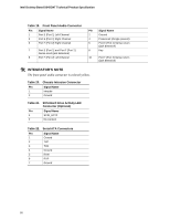
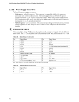
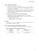
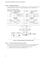
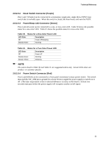
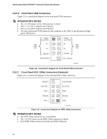
Technical Reference 2.8.2.5.2 Reset Switch Connector [Purple] Pins 5 and 7 [Purple] can be connected to a momentary single pole, single throw (SPST) type switch that is normally open. When the switch is closed, the board resets and runs the POST. 2.8.2.5.3 Power/Sleep LED Connector [Green] Pins 2 and 4 [Green] can be connected to a one- or two-color LED. Table 30 shows the possible states for a one-color LED. Table 31 shows the possible states for a two-color LED. Table 30. States for a One-Color Power LED LED State Off Steady Green Description Power off/sleeping Running Table 31. States for a Two-Color Power LED LED State Off Steady Green Steady Yellow Description Power off Running Sleeping NOTE The colors listed in Table 30 and Table 31 are suggested colors only. Actual LED colors are product- or customer-specific. 2.8.2.5.4 Power Switch Connector [Red] Pins 6 and 8 [Red] can be connected to a front panel momentary-contact power switch. The switch must pull the SW_ON# pin to ground for at least 50 ms to signal the power supply to switch on or off. (The time requirement is due to internal debounce circuitry on the board.) At least two seconds must pass before the power supply will recognize another on/off signal. 65
-
 1
1 -
2
-
3
-
4
-
5
-
6
-
7
-
8
-
9
-
10
-
11
-
12
-
13
-
14
-
15
-
16
-
17
-
18
-
19
-
20
-
21
-
22
-
23
-
24
-
25
-
26
-
27
-
28
-
29
-
30
-
31
-
32
-
33
-
34
-
35
-
36
-
37
-
38
-
39
-
40
-
41
-
42
-
43
-
44
-
45
-
46
-
47
-
48
-
49
-
50
-
51
-
52
-
53
-
54
-
55
-
56
-
57
-
58
-
59
-
 60
60 -
 61
61 -
 62
62 -
 63
63 -
 64
64 -
 65
65 -
 66
66 -
 67
67 -
 68
68 -
 69
69 -
 70
70 -
71
-
72
-
73
-
74
-
75
-
76
-
77
-
78
-
79
-
80
-
81
-
82
-
83
-
84
-
85
-
86
-
87
-
88
-
89
-
90
-
91
-
92
-
93
-
94
 |
 |