Intel BLKDQ35MPE Product Guide - Page 51
Connecting to the Internal Headers
 |
View all Intel BLKDQ35MPE manuals
Add to My Manuals
Save this manual to your list of manuals |
Page 51 highlights
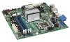
Installing and Replacing Desktop Board Components Connecting to the Internal Headers Before connecting cables to the internal headers, observe the precautions in "Before You Begin" on page 31. Figure 23 shows the location of the internal headers. Item Description A HD Audio Link B Front Panel Audio C Chassis intrusion D Serial Port Item Description E Front Panel F Alternate Front Panel Power LED G USB 2.0 (3) Figure 23. Internal Headers 51
-
 1
1 -
2
-
3
-
4
-
5
-
6
-
7
-
8
-
9
-
10
-
11
-
12
-
13
-
14
-
15
-
16
-
17
-
18
-
19
-
20
-
21
-
22
-
23
-
24
-
25
-
26
-
27
-
28
-
29
-
30
-
31
-
32
-
33
-
34
-
35
-
36
-
37
-
38
-
39
-
40
-
41
-
42
-
43
-
44
-
45
-
 46
46 -
 47
47 -
 48
48 -
 49
49 -
 50
50 -
 51
51 -
 52
52 -
 53
53 -
 54
54 -
 55
55 -
 56
56 -
57
-
58
-
59
-
60
-
61
-
62
-
63
-
64
-
65
-
66
-
67
-
68
-
69
-
70
-
71
-
72
-
73
-
74
-
75
-
76
-
77
-
78
-
79
-
80
-
81
-
82
-
83
-
84
-
85
-
86
-
87
-
88
 |
 |

Installing and Replacing Desktop Board Components
51
Connecting to the Internal Headers
Before connecting cables to the internal headers, observe the precautions in “Before
You Begin” on page 31.
Figure 23 shows the location of the internal headers.
Item
Description
Item
Description
A
HD Audio Link
E
Front Panel
B
Front Panel Audio
F
Alternate Front Panel Power LED
C
Chassis intrusion
G
USB 2.0 (3)
D
Serial Port
Figure 23.
Internal Headers