Intel BOXD410PT Product Guide - Page 35
Connecting to the Front Panel USB 2.0 Headers
 |
View all Intel BOXD410PT manuals
Add to My Manuals
Save this manual to your list of manuals |
Page 35 highlights
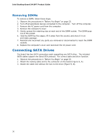
Installing and Replacing Desktop Board Components Connecting to the Front Panel USB 2.0 Headers Before connecting to the USB 2.0 headers, observe the precautions in "Before You Begin" on page 23. See Figure 10, D on page 32 for the location of the USB 2.0 headers. Table 10 shows the pin assignments for the headers. Table 10. Front Panel USB Header Pin Signal Name Pin 1 +5 VDC 2 3 D- 4 5 D+ 6 7 Ground 8 9 KEY (no pin) 10 Signal Name +5 VDC DD+ Ground No Connect Connecting a Chassis Fan Figure 11 shows the location of the chassis fan header. Connect the chassis fan cable to this header. Figure 11. Location of the Chassis Fan Header 35
-
 1
1 -
2
-
3
-
4
-
5
-
6
-
7
-
8
-
9
-
10
-
11
-
12
-
13
-
14
-
15
-
16
-
17
-
18
-
19
-
20
-
21
-
22
-
23
-
24
-
25
-
26
-
27
-
28
-
29
-
 30
30 -
 31
31 -
 32
32 -
 33
33 -
 34
34 -
 35
35 -
 36
36 -
 37
37 -
 38
38 -
 39
39 -
 40
40 -
41
-
42
-
43
-
44
-
45
-
46
-
47
-
48
-
49
-
50
-
51
-
52
-
53
-
54
-
55
-
56
-
57
-
58
-
59
-
60
-
61
-
62
 |
 |

Installing and Replacing Desktop Board Components
35
Connecting to the Front Panel USB 2.0 Headers
Before connecting to the USB 2.0 headers, observe the precautions in "Before You
Begin" on page 23.
See Figure 10, D on page 32 for the location of the USB 2.0
headers.
Table 10 shows the pin assignments for the headers.
Table 10. Front Panel USB Header
Pin
Signal Name
Pin
Signal Name
1
+5 VDC
2
+5 VDC
3
D-
4
D-
5
D+
6
D+
7
Ground
8
Ground
9
KEY (no pin)
10
No Connect
Connecting a Chassis Fan
Figure 11 shows the location of the chassis fan header.
Connect the chassis fan cable
to this header.
Figure 11.
Location of the Chassis Fan Header