Intel BOXD510MO Product Guide - Page 38
Connecting to the Front Panel Header, Table 12. Front Panel Header Signal Names
 |
View all Intel BOXD510MO manuals
Add to My Manuals
Save this manual to your list of manuals |
Page 38 highlights
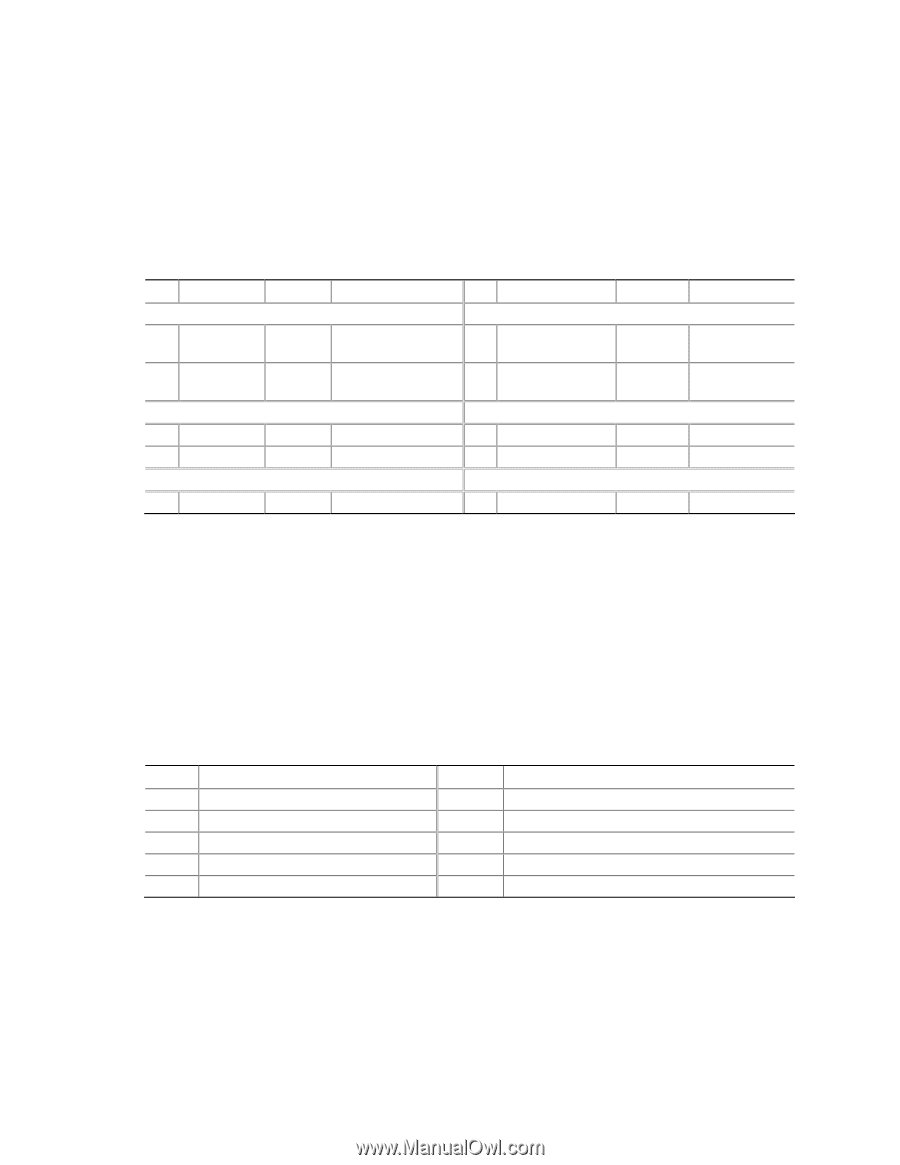
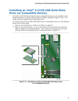
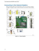
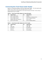
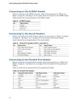
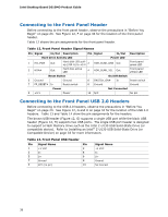
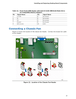
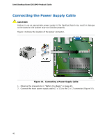
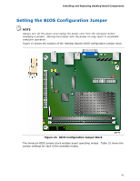
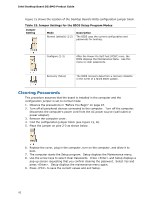
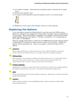
Intel Desktop Board D510MO Product Guide Connecting to the Front Panel Header Before connecting to the front panel header, observe the precautions in "Before You Begin" on page 23. See Figure 12, F on page 34 for the location of the front panel header. Table 12 shows the pin assignments for the front panel header. Table 12. Front Panel Header Signal Names Pin Signal In/Out Description Pin Signal In/Out Hard Drive Activity LED Power LED 1 HD_PWR Out Hard disk LED pullup (330 Ω) to +5 V 2 HDR_BLNK_GRN Out 3 HDA# Out Hard disk active LED 4 HDR_BLNK_YEL Out Description Front panel green LED Front panel yellow LED Reset Switch On/Off Switch 5 Ground 7 FP_RESET# In Ground Reset switch 6 SWITCH_ON# In 8 Ground Power switch Ground Power Not Connected 9 +5 V Power 10 N/C No pin Connecting to the Front Panel USB 2.0 Headers Before connecting to the USB 2.0 headers, observe the precautions in "Before You Begin" on page 23. See Figure 12, G and H on page 34 for the location of the USB 2.0 headers. Table 13 and Table 14 show the pin assignments for the headers. The brown USB header (Figure 12, G) supports a single USB port while the black USB header (Figure 12, H) supports two USB ports. The single USB port header is designed to support a Flash Memory Drive such as the Intel Z-U130 USB Solid-State Drive (or compatible device). Refer to Installing an Intel® Z-U130 USB Solid-State Drive (or Compatible Device) on page 33 for more information. Table 13. Front Panel USB Header Pin Signal Name Pin 1 +5 VDC 2 3 D- 4 5 D+ 6 7 Ground 8 9 KEY (no pin) 10 Signal Name +5 VDC DD+ Ground No Connect 38
-
 1
1 -
2
-
3
-
4
-
5
-
6
-
7
-
8
-
9
-
10
-
11
-
12
-
13
-
14
-
15
-
16
-
17
-
18
-
19
-
20
-
21
-
22
-
23
-
24
-
25
-
26
-
27
-
28
-
29
-
30
-
31
-
32
-
 33
33 -
 34
34 -
 35
35 -
 36
36 -
 37
37 -
 38
38 -
 39
39 -
 40
40 -
 41
41 -
 42
42 -
 43
43 -
44
-
45
-
46
-
47
-
48
-
49
-
50
-
51
-
52
-
53
-
54
-
55
-
56
-
57
-
58
-
59
-
60
-
61
-
62
-
63
-
64
-
65
-
66
 |
 |