Intel BX80570E8400 Mechanical Design Guidelines - Page 22
System Thermal Solution Considerations
 |
UPC - 735858199643
View all Intel BX80570E8400 manuals
Add to My Manuals
Save this manual to your list of manuals |
Page 22 highlights
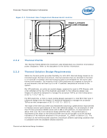
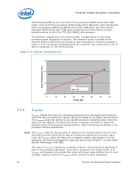
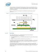
Processor Thermal/Mechanical Information 2.4 System Thermal Solution Considerations 2.4.1 Chassis Thermal Design Capabilities The Intel reference thermal solutions and Intel Boxed Processor thermal solutions assume that the chassis delivers a maximum TA at the inlet of the processor fan heatsink. The following tables show the TA requirements for the reference solutions and Intel Boxed Processor thermal solutions. Table 2-1. Heatsink Inlet Temperature of Intel® Reference Thermal Solutions Topic ATX E18764-0011 BTX Type II Heatsink Inlet Temperature 40 °C 35.5 °C NOTE: 1. Intel reference designs (E18764-001) for ATX assume the use of the thermally advantaged chassis (refer to Thermally Advantaged Chassis (TAC) Design Guide for TAC thermal and mechanical requirements). The TAC 2.0 Design Guide defines a new processor cooling solution inlet temperature target of 40 °C. The existing TAC 1.1 chassis can be compatible with TAC 2.0 guidelines. Table 2-2. Heatsink Inlet Temperature of Intel® Boxed Processor Thermal Solutions Topic Boxed Processor for Intel® Core™2 Duo Processor E8000, E7000 Series, Intel® Pentium® Dual-Core Processor E6000, E5000 Series, and Intel® Celeron® Processor E3000 Series Heatsink Inlet Temperature 40 °C NOTE: 1. Boxed Processor thermal solutions for ATX assume the use of the thermally advantaged chassis (refer to Thermally Advantaged Chassis (TAC) Design Guide for TAC thermal and mechanical requirements). The TAC 2.0 Design Guide defines a new processor cooling solution inlet temperature target of 40 °C. The existing TAC 1.1 chassis can be compatible with TAC 2.0 guidelines. 2.4.2 Improving Chassis Thermal Performance The heat generated by components within the chassis must be removed to provide an adequate operating environment for both the processor and other system components. Moving air through the chassis brings in air from the external ambient environment and transports the heat generated by the processor and other system components out of the system. The number, size and relative position of fans and vents determine the chassis thermal performance, and the resulting ambient temperature around the processor. The size and type (passive or active) of the thermal solution and the amount of system airflow can be traded off against each other to meet specific system design constraints. Additional constraints are board layout, spacing, component placement, acoustic requirements, and structural considerations that limit the thermal solution size. For more information, refer to the Performance ATX Desktop System Thermal Design Suggestions or Performance microATX Desktop System Thermal Design Suggestions or Balanced Technology Extended (BTX) System Design Guide documents available on the http://www.formfactors.org/ web site. 22 Thermal and Mechanical Design Guidelines
-
 1
1 -
2
-
3
-
4
-
5
-
6
-
7
-
8
-
9
-
10
-
11
-
12
-
13
-
14
-
15
-
16
-
 17
17 -
 18
18 -
 19
19 -
 20
20 -
 21
21 -
 22
22 -
 23
23 -
 24
24 -
 25
25 -
 26
26 -
 27
27 -
28
-
29
-
30
-
31
-
32
-
33
-
34
-
35
-
36
-
37
-
38
-
39
-
40
-
41
-
42
-
43
-
44
-
45
-
46
-
47
-
48
-
49
-
50
-
51
-
52
-
53
-
54
-
55
-
56
-
57
-
58
-
59
-
60
-
61
-
62
-
63
-
64
-
65
-
66
-
67
-
68
-
69
-
70
-
71
-
72
-
73
-
74
-
75
-
76
-
77
-
78
-
79
-
80
-
81
-
82
-
83
-
84
-
85
-
86
-
87
-
88
-
89
-
90
-
91
-
92
-
93
-
94
-
95
-
96
-
97
-
98
-
99
-
100
-
101
-
102
-
103
-
104
-
105
-
106
-
107
-
108
-
109
-
110
-
111
-
112
-
113
-
114
-
115
-
116
-
117
-
118
-
119
-
120
-
121
-
122
-
123
-
124
-
125
-
126
 |
 |
