Intel D845EBG2 Product Guide - Page 63
Midboard Connectors, Audio Connectors
 |
UPC - 735858153287
View all Intel D845EBG2 manuals
Add to My Manuals
Save this manual to your list of manuals |
Page 63 highlights
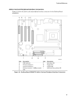
Midboard Connectors Audio Connectors Figure 14 shows the location of the audio connectors. B C 1 2 3 4 A 5 6 7 9 10 1 4 4 1 Technical Reference Item A B C Description Front panel audio (see Table 29 for pin assignments) Auxiliary line in CD-ROM Figure 14. Audio Connectors Table 29 shows the pin assignments for the front panel audio header. Table 29. Front Panel Audio Header Signal Names (J8B1) Pin Signal Name 1 AUD-MIC 3 AUD-MIC-BIAS 5 AUD-FPOUT-R 7 HP-ON 9 AUD-FPOUT-L Pin Signal Name 2 AUD-GND 4 AUD-VCC 6 AUD-RET-R 8 KEY 10 AUD-RET-L OM13661 Color Black White Black 63
-
 1
1 -
2
-
3
-
4
-
5
-
6
-
7
-
8
-
9
-
10
-
11
-
12
-
13
-
14
-
15
-
16
-
17
-
18
-
19
-
20
-
21
-
22
-
23
-
24
-
25
-
26
-
27
-
28
-
29
-
30
-
31
-
32
-
33
-
34
-
35
-
36
-
37
-
38
-
39
-
40
-
41
-
42
-
43
-
44
-
45
-
46
-
47
-
48
-
49
-
50
-
51
-
52
-
53
-
54
-
55
-
56
-
57
-
 58
58 -
 59
59 -
 60
60 -
 61
61 -
 62
62 -
 63
63 -
 64
64 -
 65
65 -
 66
66 -
 67
67 -
 68
68 -
69
-
70
-
71
-
72
-
73
-
74
-
75
-
76
-
77
-
78
 |
 |
Technical Reference
63
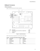
Midboard Connectors
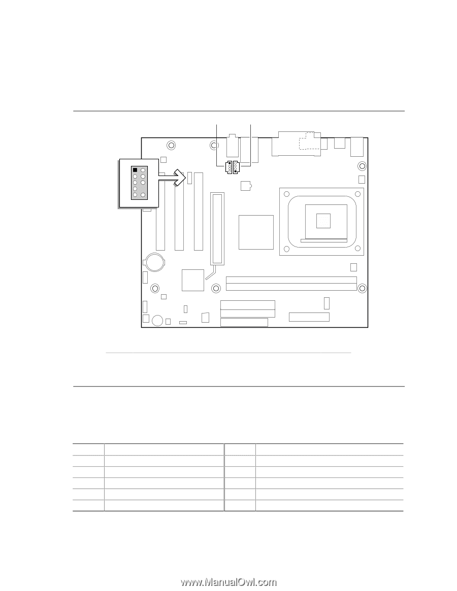
Audio Connectors
Figure 14 shows the location of the audio connectors.
OM13661
1
4
C
B
1
4
1
3
5
7
9
2
4
6
10
A
Item
Description
Color
A
Front panel audio (see Table 29 for pin assignments)
Black
B
Auxiliary line in
White
C
CD-ROM
Black
Figure 14.
Audio Connectors
Table 29 shows the pin assignments for the front panel audio header.
Table 29.
Front Panel Audio Header Signal Names (J8B1)
Pin
Signal Name
Pin
Signal Name
1
AUD-MIC
2
AUD-GND
3
AUD-MIC-BIAS
4
AUD-VCC
5
AUD-FPOUT-R
6
AUD-RET-R
7
HP-ON
8
KEY
9
AUD-FPOUT-L
10
AUD-RET-L