Intel D845GERG2 Product Guide
Intel D845GERG2 - Desktop Board Motherboard Manual
 |
UPC - 735858157803
View all Intel D845GERG2 manuals
Add to My Manuals
Save this manual to your list of manuals |
Intel D845GERG2 manual content summary:
- Intel D845GERG2 | Product Guide - Page 1
Intel® Desktop Board D845GERG2/D845GEBV2 Product Guide Order Number: A99403-001 - Intel D845GERG2 | Product Guide - Page 2
Intel® Desktop Board D845GERG2/D845GEBV2 Product Guide. Date August 2002 If an FCC declaration of conformity marking is present on the board with the instructions, may Intel may make changes to specifications and product descriptions at any time, without notice. Desktop Board D845GERG2/D845GEBV2 - Intel D845GERG2 | Product Guide - Page 3
Desktop Board Features Components...9 Processor ...11 Main Memory ...12 Intel® 845GE Chipset ...12 Intel® 82845GE Graphics and Memory Controller Hub (GMCH 13 Intel® 82801DB I/O Controller Hub (ICH4 13 Firmware Hub (FWH 13 Input/Output (I/O) Controller 13 Graphics Subsystem ...14 Audio Subsystem - Intel D845GERG2 | Product Guide - Page 4
a Front Panel Audio Solution 31 Installing a Front Panel USB Solution 32 Connecting Fans and Power Cables 33 Connecting Fans ...33 Connecting Power Cables 33 Setting the BIOS Configuration Jumper Block 34 Clearing Passwords ...35 Replacing the Battery ...36 3 Updating the BIOS Updating the BIOS - Intel D845GERG2 | Product Guide - Page 5
Instructions...75 Ensure Electromagnetic Compatibility (EMC) Compliance 75 Chassis and Component Certifications 76 Prevent Power Supply Overload 76 Place Battery Marking 76 Use Only for Intended Applications 76 Figures 1. Desktop Board D845GERG2 Components 9 2. Desktop Board D845GEBV2 - Intel D845GERG2 | Product Guide - Page 6
Intel Desktop Boards D845GERG2 and D845GEBV2 Product Guide 15. Back Panel Connectors 64 16. Audio Connectors ...65 17. PCI Bus Add-in Card and Peripheral Interface Connectors 66 Tables 1. Feature Summary ...7 2. Supported Processors 11 3. RJ-45 10/100 Ethernet LAN Connector LEDs 15 4. RJ-45 10/ - Intel D845GERG2 | Product Guide - Page 7
FSB Intel® Celeron® processor in an mPGA-478 socket • Two 184-pin, 2.5 V SDRAM Dual Inline Memory Module (DIMM) sockets • 333/266 MHz DDR SDRAM interface • Designed to support up to 2 GB of system memory Chipset I/O Control Graphics Audio LAN (optional) NOTE: Desktop Board D845GERG2/D845GEBV2 has - Intel D845GERG2 | Product Guide - Page 8
bus connector 6) BIOS • Intel/AMI BIOS • 4 Mbit symmetrical flash memory • Support for SMBIOS Power Management • Support for Advanced Configuration and Power Interface (ACPI) • Suspend to RAM (STR) support • Wake on USB, PCI, CNR, RS-232, PS/2, LAN, and front panel Hardware Management Hardware - Intel D845GERG2 | Product Guide - Page 9
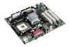
connector Y Intel 82801DB (ICH4) K DIMM sockets Z Front panel USB 2.0 header L Super I/O controller AA AGP connector M Main power connector BB PCI bus add-in card connectors N Diskette drive connector CC CNR (optional) O Secondary IDE connector Figure 1. Desktop Board D845GERG2 Components - Intel D845GERG2 | Product Guide - Page 10
Intel Desktop Board D845GERG2/D845GEBV2 Product Guide Figure 2 shows the approximate location of the major components on Desktop Board D845GEBV2. A B CD E F G CC H I BB AA Z J Y K L X WV UT S R Q PO NM OM13589 A Audio codec P Primary IDE connector B Front panel audio header Q - Intel D845GERG2 | Product Guide - Page 11
site at: http://support.intel.com/support/motherboards/desktop/ For instructions on installing or upgrading the processor, see Chapter 2 on page 21. Desktop Board D845GERG2/D845GEBV2 requires an ATX12V compliant power supply to function according to desktop board specifications. Both boards have two - Intel D845GERG2 | Product Guide - Page 12
Intel Desktop Board D845GERG2/D845GEBV2 Product Guide Main Memory ✏ NOTE To be fully compliant with all applicable Intel® SDRAM memory specifications, the board should be populated with DIMMs that support the Serial Presence Detect (SPD) data structure. If your memory modules do not support SPD, you - Intel D845GERG2 | Product Guide - Page 13
Board Features Intel® 82845GE Graphics and Memory Controller Hub (GMCH) The GMCH provides Intel Extreme Graphics as well as the processor, system memory, AGP, and hub interfaces in the Intel 845GE chipset platform. Features on Desktop Board D845GERG2/D845GEBV2 include: • Single processor support - Intel D845GERG2 | Product Guide - Page 14
Intel Desktop Board D845GERG2/D845GEBV2 Product Guide Graphics Subsystem The graphics subsystem features the following: • Intel 845GE chipset • Intel Extreme Graphics • 1.5 V AGP connector Audio Subsystem The audio subsystem features the following: • Intel 845GE chipset (AC '97) • Analog Devices Inc - Intel D845GERG2 | Product Guide - Page 15
to a USB front panel header. USB 2.0 ports are backward compatible with USB 1.1 devices. USB 1.1 devices will function normally at USB 1.1 speeds. USB 2.0 support requires both an operating system and drivers that fully support USB 2.0 transfer rates. Disabling Hi-Speed USB in BIOS reverts all USB - Intel D845GERG2 | Product Guide - Page 16
NOTE Desktop Board D845GERG2/D845GEBV2 is only compatible with 1.5 V AGP cards. AGP is a high-performance interface for graphics-intensive applications, such as 3D graphics. AGP is independent of the PCI bus and is intended for exclusive use with graphical display devices. The AGP connector supports - Intel D845GERG2 | Product Guide - Page 17
Desktop Board Features BIOS The BIOS provides the Power-On Self-Test (POST), the BIOS Setup program, the PCI and IDE auto-configuration utilities, and the video BIOS. The BIOS is stored in the Firmware Hub. The BIOS can be updated by following the instructions in Chapter 3 on page 39. PCI Auto - Intel D845GERG2 | Product Guide - Page 18
Intel Desktop Board D845GERG2/D845GEBV2 Product Guide ACPI ACPI gives the operating system direct control over the power management and Plug & Play functions of a computer. The use of ACPI with the desktop board requires an operating system that provides full ACPI support. Suspend to RAM (Instantly - Intel D845GERG2 | Product Guide - Page 19
. If the standby current necessary to support multiple wake events from the PCI and/or USB buses exceeds power supply capacity, the desktop board may lose register settings stored in memory. For more information on standby current requirements for these desktop boards, refer to the TPS by selecting - Intel D845GERG2 | Product Guide - Page 20
Intel Desktop Board D845GERG2/D845GEBV2 Product Guide Resume on Ring The operation of Resume on Ring Power-On Self-Test (POST). Battery A battery on the desktop board keeps the values in CMOS RAM and the clock current when the computer is turned off. See Chapter 2 starting on page 21 for instructions - Intel D845GERG2 | Product Guide - Page 21
remove the desktop board • Install and remove a processor • Install and remove memory • Install and remove an AGP or ADD card • Connect the IDE cable • Connect the front panel header • Install the front panel audio solution • Install the front panel USB solution • Connect fans • Connect power cables - Intel D845GERG2 | Product Guide - Page 22
Intel Desktop Board D845GERG2/D845GEBV2 Product Guide Installing the I/O Shield The desktop board comes with an I/O shield. When correct airflow within the chassis. Install the I/O shield before installing the desktop board in the chassis. Place the shield inside the chassis as shown in Figure - Intel D845GERG2 | Product Guide - Page 23
precautions. Refer to your chassis manual for instructions on installing and removing the desktop board. Figure 5 shows the location of the eight mounting holes for Desktop Board D845GEBV2. Desktop Board D845GERG2 has six mounting holes. OM13593 Figure 5. Location of Desktop Board Mounting Holes 23 - Intel D845GERG2 | Product Guide - Page 24
Desktop Board D845GERG2/D845GEBV2 has an integrated processor fan heat sink retention mechanism (RM). For instructions on how to install the processor fan heat sink to the integrated processor fan heat sink RM, refer to the boxed processor manual or the Intel World Wide Web site at: http://support - Intel D845GERG2 | Product Guide - Page 25
Heat Sink Cable to the Processor Fan Connector Removing the Processor For instruction on how to remove the processor fan heat sink and processor, refer to the processor installation manual or the Intel World Wide Web site at: http://support.intel.com/support/processors/pentium4/intnotes478.htm 25 - Intel D845GERG2 | Product Guide - Page 26
with all applicable Intel SDRAM memory specifications, the boards require DIMMs that support the Serial Presence Detect (SPD) data structure. You can access the PC Serial Presence Detect Specification at: http://www.intel.com/technology/memory/pcsdram/spec/ Desktop Board D845GERG2/D845GEBV2 has two - Intel D845GERG2 | Product Guide - Page 27
. Replace the computer's cover and reconnect the AC power cord. Removing DIMMs To remove a memory module, follow these steps: 1. Observe the precautions power supply, certain board components and/or traces may be damaged. The AGP connector supports 1.5 V 4X and 2X AGP or ADD cards. The desktop board - Intel D845GERG2 | Product Guide - Page 28
Intel Desktop Board D845GERG2/D845GEBV2 Product Guide Installing an AGP or ADD Card Follow these instructions to install an AGP or Secure the card's metal bracket to the chassis back panel with a screw. Removing the AGP or ADD Card Follow these instructions to remove the AGP or ADD card from the RM - Intel D845GERG2 | Product Guide - Page 29
IDE Cable The Intel® boxed desktop board package includes two IDE cables. Either cable can connect two drives to the desktop board. The cables support the Ultra DMA-33 and ATA-66/100 transfer protocols. Figure 10 shows the correct installation of the cable. ✏ NOTE ATA-66/100 compatible cables are - Intel D845GERG2 | Product Guide - Page 30
Intel Desktop Board D845GERG2/D845GEBV2 Product Guide Connecting Front Panel Headers Before connecting the front panel header, observe the precautions in "Before You Begin" on page 21. 1 2 3 4 A5 6 7 9 10 1 2 3 4 B5 6 7 8 10 1 2 3 4 C5 6 7 8 9 D Item A B C D Description - Intel D845GERG2 | Product Guide - Page 31
switch Power 6 SWITCH_ON# In 8 Ground 10 N/C Power switch Ground Not connected Installing a Front Panel Audio Solution Figure 11 A on page 30 shows the location of the front panel audio header. Table 6 shows the pin assignments for the front panel audio header. Table 6. Front Panel Audio Header - Intel D845GERG2 | Product Guide - Page 32
Intel Desktop Board D845GERG2/D845GEBV2 Product Guide To restore back panel operations, follow these steps: 1. Observe the precautions in "Before You Begin" on page 21. 2. Turn off all peripheral devices connected to the computer. Turn off the computer and disconnect the AC power cord. 3. Remove - Intel D845GERG2 | Product Guide - Page 33
Installing and Replacing Desktop Board Components Connecting Fans and Power Cables Figure 12 shows the location of the fans and power supply connectors. 1 Chassis rear fan 12 V processor core voltage connector 1 Processor fan 1 Chassis front fan 1 Main power connector 1 OM14775 Figure 12. - Intel D845GERG2 | Product Guide - Page 34
Intel Desktop Board D845GERG2/D845GEBV2 Product Guide Setting the BIOS Configuration Jumper Block CAUTION Always turn off the power and unplug the power cord from the computer before changing the jumper. Moving the jumper with the power on may result in unreliable computer operation. The location of - Intel D845GERG2 | Product Guide - Page 35
assumes that the board is installed in the computer and the configuration jumper block is set to normal mode. 1. Observe the precautions in "Before You Begin" on page 21. 2. Turn off all peripheral devices connected to the computer. Turn off the computer. Disconnect the computer's power cord from - Intel D845GERG2 | Product Guide - Page 36
Intel Desktop Board D845GERG2/D845GEBV2 Product Guide Replacing the Battery A coin-cell battery (CR2032) powers the real-time clock and CMOS memory. When the computer is not plugged into a wall socket, the battery has an estimated life of three years. When the computer is plugged in, the - Intel D845GERG2 | Product Guide - Page 37
Installing and Replacing Desktop Board Components VORSICHT Bei falschem Einsetzen einer neuen Batterie besteht Explosionsgefahr. Die Batterie darf nur durch denselben oder einen entsprechenden, vom Hersteller empfohlenen Batterietyp ersetzt werden. - Intel D845GERG2 | Product Guide - Page 38
Intel Desktop Board D845GERG2/D845GEBV2 Product Guide To replace the battery, follow these steps: 1. Observe the precautions in "Before You Begin" (see page 21). 2. Turn off all peripheral devices connected to the computer. Disconnect the computer's power cord from the AC power source (wall outlet - Intel D845GERG2 | Product Guide - Page 39
Flash Memory Update Utility and the ease-of use of Windows-based installation wizards. To update the BIOS with the Intel Express BIOS Update utility: 1. Go to the Intel World Wide Web site: http://support.intel.com/support/motherboards/desktop/ 2. Navigate to the Desktop Board D845GERG2 or D845GEBV2 - Intel D845GERG2 | Product Guide - Page 40
Board D845GERG2 or D845GEBV2 page on the Intel World Wide Web site: http://support.intel.com/support/motherboards/desktop ✏ NOTE Please review the instructions distributed with the update utility before attempting a BIOS update. The Intel Flash Memory Update Utility allows you to: • Update the BIOS - Intel D845GERG2 | Product Guide - Page 41
explain how to recover the BIOS if an update fails. The following procedure uses recovery mode for the Setup program. See page 34 for more information on Setup modes. ✏ NOTE Because of the small amount of code available in the boot block area, there is no video support. You will not see anything - Intel D845GERG2 | Product Guide - Page 42
Intel Desktop Board D845GERG2/D845GEBV2 Product Guide 42 - Intel D845GERG2 | Product Guide - Page 43
to the Intel® Desktop Board D845GERG2/D845GEBV2 Technical Product Specification or the Intel World Wide Web site: http://support.intel.com/support/motherboards/desktop ✏ NOTE For reference purposes, you should write down the current Setup settings. When you make changes to the settings, update this - Intel D845GERG2 | Product Guide - Page 44
Intel Desktop Board D845GERG2/D845GEBV2 Product Guide Table 10 shows the function keys available for menu screens. Table 10. BIOS Setup Program Function Keys BIOS Setup Program Function Key or or Description Selects a different menu screen Moves cursor up - Intel D845GERG2 | Product Guide - Page 45
Security Power Boot Exit Table 12 describes the Main Menu. This menu reports processor and memory information and is used to configure the system date and system time. Table 12. Main Menu Feature BIOS Version Processor Type Processor Speed System Bus Speed System Memory Speed Cache RAM - Intel D845GERG2 | Product Guide - Page 46
Intel Desktop Board D845GERG2/D845GEBV2 Product Guide Advanced Menu Maintenance Main Advanced Security Power Boot Exit PCI Configuration Boot Configuration Peripheral Configuration IDE Configuration Diskette Configuration Event Log Configuration Video Configuration USB Configuration Chipset - Intel D845GERG2 | Product Guide - Page 47
Using the BIOS Setup Program PCI Configuration Submenu Maintenance Main Advanced Security Power Boot Exit PCI Configuration The submenu shown in Table 14 is used to configure the IRQ priority of PCI slots individually. Table 14. PCI Configuration - Intel D845GERG2 | Product Guide - Page 48
Intel Desktop Board D845GERG2/D845GEBV2 Product Guide Boot Configuration Submenu Maintenance Main Advanced Security Power Boot Exit Boot Configuration The submenu shown in Table 15 is used to set the Plug & Play options and the power-on state of the Numlock key. Table 15. Boot - Intel D845GERG2 | Product Guide - Page 49
BIOS Setup Program Peripheral Configuration Submenu Maintenance Main Advanced Security Power Description Configures serial port A. Auto assigns the first free COM port, normally COM1, the address 3F8h, Only operates in AT†-compatible mode. Bi-directional operates in PS/2-compatible mode. EPP is - Intel D845GERG2 | Product Guide - Page 50
Intel Desktop Board D845GERG2/D845GEBV2 Product Guide Table 16. Peripheral Configuration Submenu (continued) Feature Base I/O Address (This feature is present only when Parallel Port is set to Enabled) Interrupt (This feature is present only when Parallel Port is set to Enabled) Audio LAN Device ( - Intel D845GERG2 | Product Guide - Page 51
Using the BIOS Setup Program IDE Configuration Submenu Maintenance Main Advanced Security Power Boot Exit IDE Disk Pre-Delay • Disabled (default) Specifies the hard disk drive pre-delay. Causes the BIOS to • 3 Seconds • 6 Seconds insert a delay before attempting to detect IDE drives in - Intel D845GERG2 | Product Guide - Page 52
Intel Desktop Board D845GERG2/D845GEBV2 Product Guide Primary/Secondary IDE Master/Slave Submenus Maintenance Main Advanced Security Power Block Mode • Disabled • Auto (default) Check the hard disk drive's specifications for optimum setting. PIO Mode (Note) DMA Mode S.M.A.R.T. Cable Detected - Intel D845GERG2 | Product Guide - Page 53
Using the BIOS Setup Program Diskette Configuration Submenu Maintenance Main Advanced Security Power Boot Exit Diskette write protection. Event Log Configuration Submenu Maintenance Main Advanced Security Power Boot Exit Event Log Configuration The submenu shown in Table - Intel D845GERG2 | Product Guide - Page 54
Intel Desktop Board D845GERG2/D845GEBV2 Product Guide Video Configuration Submenu Maintenance Main Advanced Security Power Boot Exit Video Configuration The submenu shown in Table 21 is used to configure video features. Table 21. Video Configuration Submenu Feature Options Graphics - Intel D845GERG2 | Product Guide - Page 55
Using the BIOS Setup Program Chipset Configuration Submenu Maintenance Main Advanced Security Power Boot Exit Chipset Configuration The menu shown in Table 23 is used to configure advanced chipset features. Table 23. Chipset Configuration Submenu Feature Options ISA Enable Bit PCI - Intel D845GERG2 | Product Guide - Page 56
Intel Desktop Board D845GERG2/D845GEBV2 Product Guide Hardware Management Submenu Maintenance Main Advanced Security Power Boot Exit Hardware Management The menu shown in Table 24 is used to configure hardware management features. Table 24. Hardware Management Feature Fan Control Lowest - Intel D845GERG2 | Product Guide - Page 57
in Table 27 is for setting the ACPI features. Table 27. ACPI Submenu Feature ACPI Suspend Mode Wake on LAN from S5 Options • S1 State (default) • S3 State • Stay Off (default) • Power On Description Specifies the ACPI sleep state. In ACPI soft-off mode only, determines how the system responds to - Intel D845GERG2 | Product Guide - Page 58
Intel Desktop Board D845GERG2/D845GEBV2 Product Guide Boot Menu Maintenance Main Advanced Security Power Boot Exit Boot Device Priority Hard Disk Drives Removable Devices ATAPI CD-ROM Drives The menu shown in Table 28 is used to set the - Intel D845GERG2 | Product Guide - Page 59
first through final boot devices are, respectively listed below. The BIOS supports up to sixteen total boot devices in any combination of the (maximum of four). Hard Disk Drives Submenu Maintenance Main Advanced Security Power The submenu shown in Table 30 is for setting hard disk drives. - Intel D845GERG2 | Product Guide - Page 60
Intel Desktop Board D845GERG2/D845GEBV2 Product Guide Removable Devices Submenu Maintenance Main Advanced Security Power The the maximum number of removable devices supported by the BIOS. ATAPI CD-ROM Drives Maintenance Main Advanced Security Power Boot Exit ATAPI CD-ROM Drives - Intel D845GERG2 | Product Guide - Page 61
Menu Maintenance Main Advanced Security Power Boot Exit The menu shown in Table 33 is used to exit the BIOS Setup program, saving changes, BIOS reads the Setup values from flash memory. If this memory is corrupted, the BIOS reads the custom defaults. If no custom defaults are set, the BIOS - Intel D845GERG2 | Product Guide - Page 62
Intel Desktop Board D845GERG2/D845GEBV2 Product Guide 62 - Intel D845GERG2 | Product Guide - Page 63
This chapter shows the location of the: • Back panel connectors • Audio connectors • Add-in board and peripheral interface connectors CAUTION Many of the midboard and front panel connectors provide operating voltage (+5 V dc and +12 V dc, for example) to devices inside the computer chassis - Intel D845GERG2 | Product Guide - Page 64
Intel Desktop Board D845GERG2/D845GEBV2 Product Guide Back Panel Connectors Figure 15 shows the back panel connectors. A E H C BD F G Item A B C D E F G H I J K L M Description PS/2 mouse port PS/2 keyboard port USB 2.0 port USB 2.0 port Parallel port Serial port VGA port RJ-45 (optional) - Intel D845GERG2 | Product Guide - Page 65
Audio Connectors Figure 11 shows the approximate location of the audio connectors. BC 1 2 3 4 A5 6 7 9 10 4 1 4 1 Technical Reference Item A B C Description Color Front panel audio Auxiliary line in (ATAPI) CD-ROM (ATAPI) Black Grey Black Figure 16. Audio Connectors OM13612 65 - Intel D845GERG2 | Product Guide - Page 66
Intel Desktop Board D845GERG2/D845GEBV2 Product Guide Add-In Card and Peripheral Interface Connectors Figure 17 shows the PCI bus add-in card and peripheral interface connectors for Desktop Board D845GEBV2. Desktop Board D845GERG2 has three PCI bus add-in card connectors. AB C D E F G H 2 40 1 - Intel D845GERG2 | Product Guide - Page 67
Technical Reference Desktop Board Resources Memory Map Table 34. System Memory Map Address Memory Runtime BIOS Reserved Available high DOS memory (open to the PCI bus) Video memory and BIOS Extended BIOS data (movable by memory manager software) Extended conventional memory Conventional memory - Intel D845GERG2 | Product Guide - Page 68
Intel Desktop Board D845GERG2/D845GEBV2 Product Guide Interrupts Table 36. Interrupts IRQ System Resource NMI I/O channel check 0 Reserved, interval timer 1 Reserved, keyboard buffer full 2 Reserved, cascade interrupt from slave PIC 3 COM2* 4 COM1* 5 - Intel D845GERG2 | Product Guide - Page 69
Board D845GERG2/D845GEBV2 reports POST errors in two ways: • By sounding a beep code • By displaying an error message on the monitor BIOS Beep Codes The BIOS beep codes are listed in Table 37. The BIOS also issues a beep code (one long tone followed by two short tones) during POST if the video - Intel D845GERG2 | Product Guide - Page 70
Intel Desktop Board D845GERG2/D845GEBV2 Product Guide BIOS Error Messages When a recoverable error occurs during the POST, the BIOS displays an error message describing the problem. Table 38. BIOS battery may be losing power. Replace the battery is incorrect. CMOS memory may have been corrupted - Intel D845GERG2 | Product Guide - Page 71
Error Messages and Indicators Table 38. BIOS Error Messages (continued) Error Message Memory Size Decreased Memory Size Increased Memory Size Changed No Boot Device Available Off Board Parity Error On Board Parity Error Parity Error NVRAM / CMOS / PASSWORD cleared by Jumper Pressed - Intel D845GERG2 | Product Guide - Page 72
Intel Desktop Board D845GERG2/D845GEBV2 Product Guide 72 - Intel D845GERG2 | Product Guide - Page 73
compatibility (EMC) regulations, and product certification markings for Desktop Board D845GERG2/D845GEBV2. • Instructions and precautions for integrators who are installing the desktop board in a chassis. Safety Regulations Desktop Board D845GERG2/D845GEBV2 Compatibility. (Australia and New Zealand - Intel D845GERG2 | Product Guide - Page 74
Intel Desktop Board D845GERG2/D845GEBV2 Product Guide Product Certification Markings Desktop Board D845GERG2/D845GEBV2 has the following product certification markings: • UL joint US/Canada Recognized Component mark: consists of small c followed by a stylized backward UR and followed by a small - Intel D845GERG2 | Product Guide - Page 75
. Ensure Electromagnetic Compatibility (EMC) Compliance Before computer integration, make sure that the power supply and other modules or peripherals, as applicable, have passed Class B EMC testing and are marked accordingly. In the installation instructions for the host chassis, power supply, and - Intel D845GERG2 | Product Guide - Page 76
Intel Desktop Board D845GERG2/D845GEBV2 Product Guide Chassis and Component Certifications Ensure that the chassis and certain components; such as the power at the front of this product guide demonstrates compliance instructions. Use Only for Intended Applications All Intel desktop processor boards
-
 1
1 -
 2
2 -
 3
3 -
 4
4 -
 5
5 -
 6
6 -
 7
7 -
8
-
9
-
10
-
11
-
12
-
13
-
14
-
15
-
16
-
17
-
18
-
19
-
20
-
21
-
22
-
23
-
24
-
25
-
26
-
27
-
28
-
29
-
30
-
31
-
32
-
33
-
34
-
35
-
36
-
37
-
38
-
39
-
40
-
41
-
42
-
43
-
44
-
45
-
46
-
47
-
48
-
49
-
50
-
51
-
52
-
53
-
54
-
55
-
56
-
57
-
58
-
59
-
60
-
61
-
62
-
63
-
64
-
65
-
66
-
67
-
68
-
69
-
70
-
71
-
72
-
73
-
74
-
75
-
76
 |
 |

Intel
®
Desktop Board
D845GERG2/D845GEBV2
Product Guide
Order Number:
A99403-001