Intel D845GLLY Product Guide - Page 27
Setting the Front Panel USB Wake Configuration Jumper Block
 |
View all Intel D845GLLY manuals
Add to My Manuals
Save this manual to your list of manuals |
Page 27 highlights
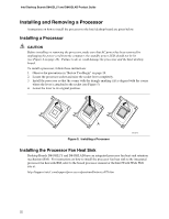
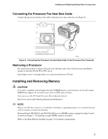
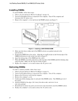
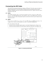
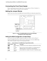
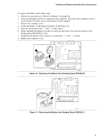
Installing and Replacing Desktop Board Components Setting the Front Panel USB Wake Configuration Jumper Block The 3-pin front panel USB wake configuration jumper block, labeled J9F1, enables configuration of the two front panel USB ports. Table 5. Jumper Settings for the Front Panel USB Wake Configuration Jumper Block (J9F1) Jumper Setting 1-2 13 Configuration Allows wake from ACPI state S1. 2-3 13 Allows wake from front panel USB ports in all ACPI states (must also set ACPI BIOS option to S3). None 13 Disables front panel USB. Installing a Front Panel Audio Solution (Optional) To install the cable that connects the front panel audio solution to the front panel audio header, follow these steps: 1. Observe the precautions in "Before You Begin" on page 19. 2. Turn off all peripheral devices connected to the computer. Turn off the computer and disconnect the AC power cord. 3. Remove the cover. Locate the front panel audio header (J8A1), see Figure 13 on page 61. 4. Remove the two jumpers from the header (this disables the back panel audio connectors). 5. Install a correctly keyed and shielded front panel audio cable. 6. Connect the audio cable to the front panel audio solution. 7. Replace the cover. To restore back panel operations, follow these steps: 1. Observe the precautions in "Before You Begin" on page 19. 2. Turn off all peripheral devices connected to the computer. Turn off the computer and disconnect the AC power cord. 3. Remove the cover. Remove the front panel audio cable. 4. Install a jumper on pins 5-6 (rear R channel). 5. Install a jumper on pins 9-10 (rear L channel). 6. Replace the cover. Installing a Front Panel USB Solution Before installing a front panel USB 2.0 solution, observe the precautions in "Before You Begin" on page 19. Refer to Table 31 on page 65 for pin assignments. 27
-
 1
1 -
2
-
3
-
4
-
5
-
6
-
7
-
8
-
9
-
10
-
11
-
12
-
13
-
14
-
15
-
16
-
17
-
18
-
19
-
20
-
21
-
 22
22 -
 23
23 -
 24
24 -
 25
25 -
 26
26 -
 27
27 -
 28
28 -
 29
29 -
 30
30 -
 31
31 -
 32
32 -
33
-
34
-
35
-
36
-
37
-
38
-
39
-
40
-
41
-
42
-
43
-
44
-
45
-
46
-
47
-
48
-
49
-
50
-
51
-
52
-
53
-
54
-
55
-
56
-
57
-
58
-
59
-
60
-
61
-
62
-
63
-
64
-
65
-
66
-
67
-
68
-
69
-
70
-
71
-
72
-
73
-
74
-
75
-
76
 |
 |
