Intel D845PESV Product Guide - Page 31
Connecting the Front Panel Header, Installing a Front Panel Audio Solution, Hard Drive Activity LED
 |
UPC - 735858156738
View all Intel D845PESV manuals
Add to My Manuals
Save this manual to your list of manuals |
Page 31 highlights
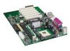
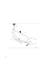
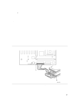
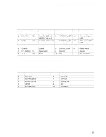
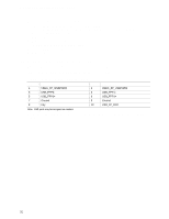
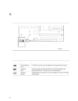
Installing and Replacing Desktop Board Components Connecting the Front Panel Header Before connecting the front panel header, observe the precautions in "Before You Begin" on page 21. Figure 10, C on page 30 shows the location of the front panel header. Table 4 shows the pin assignments for the front panel header. Table 4. Front Panel Header (J9G1) Pin Signal In/Out Description Hard Drive Activity LED Pin Signal In/Out Description Power LED 1 HD_PWR 3 HDA# Out Hard disk LED pull- 2 HDR_BLNK_GRN Out Front panel green up (330 Ω) to +5 V LED Out Hard disk active LED 4 HDR_BLNK_YEL Out Front panel yellow LED Reset Switch On/Off Switch 5 Ground 7 FP_RESET# In 9 +5 V Out Ground Reset switch Power 6 SWITCH_ON# In 8 Ground 10 N/C Power switch Ground Not connected Installing a Front Panel Audio Solution Figure 10, A on page 30 shows the location of the front panel audio header. Table 5 shows the pin assignments for the front panel audio header. Table 5. Front Panel Audio Header Signal Names (J8A1) Pin Signal Name 1 AUD-MIC 3 AUD-MIC-BIAS 5 AUD-FPOUT-R 7 HP-ON 9 AUD-FPOUT-L Pin Signal Name 2 AUD-GND 4 AUD-VCC 6 AUD-RET-R 8 KEY 10 AUD-RET-L To install the cable that connects the front panel audio solution to the front panel audio header, follow these steps: 1. Observe the precautions in "Before You Begin" on page 21. 2. Turn off all peripheral devices connected to the computer. Turn off the computer and disconnect the AC power cord. 3. Remove the cover. 4. Locate the front panel audio header (J8A1), see Figure 10, A on page 30. 5. Remove the two jumpers from the header to disable the back panel audio connectors. 6. Install a correctly keyed and shielded front panel audio cable. 7. Connect the audio cable to the front panel audio solution. 8. Replace the cover. 31
-
 1
1 -
2
-
3
-
4
-
5
-
6
-
7
-
8
-
9
-
10
-
11
-
12
-
13
-
14
-
15
-
16
-
17
-
18
-
19
-
20
-
21
-
22
-
23
-
24
-
25
-
 26
26 -
 27
27 -
 28
28 -
 29
29 -
 30
30 -
 31
31 -
 32
32 -
 33
33 -
 34
34 -
 35
35 -
 36
36 -
37
-
38
-
39
-
40
-
41
-
42
-
43
-
44
-
45
-
46
-
47
-
48
-
49
-
50
-
51
-
52
-
53
-
54
-
55
-
56
-
57
-
58
-
59
-
60
-
61
-
62
-
63
-
64
-
65
-
66
-
67
-
68
-
69
-
70
-
71
-
72
-
73
-
74
-
75
-
76
-
77
-
78
 |
 |
