Intel D845PESV Product Guide - Page 32
Installing a Front Panel USB Solution, Replace the cover.
 |
UPC - 735858156738
View all Intel D845PESV manuals
Add to My Manuals
Save this manual to your list of manuals |
Page 32 highlights
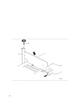
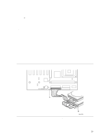
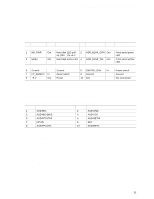
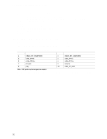
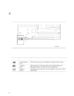
Intel Desktop Board D845PESV Product Guide To restore back panel operations, follow these steps: 1. Observe the precautions in "Before You Begin" on page 21. 2. Turn off all peripheral devices connected to the computer. Turn off the computer and disconnect the AC power cord. 3. Remove the cover. 4. Remove the front panel audio cable. 5. Install a jumper on pins 5-6 (rear R channel). 6. Install a jumper on pins 9-10 (rear L channel). 7. Replace the cover. Installing a Front Panel USB Solution Figure 10, B on page 30 shows the location of the front panel USB 2.0 header. Table 6 shows the pin assignments for the front panel USB 2.0 header. Table 6. Front Panel USB 2.0 Header (J9F1) Pin Signal name 1 VREG_FP_WSBPWR0 3 USB_FPP0- 5 USB_FPP0+ 7 Ground 9 Key Pin Signal name 2 VREG_FP_USBPWR0 4 USB_FPP1- 6 USB_FPP1+ 8 Ground 10 USB_FP_OC0 Note: USB ports may be assigned as needed. Before installing a front panel USB 2.0 solution, observe the precautions in "Before You Begin" on page 21. 32
-
 1
1 -
2
-
3
-
4
-
5
-
6
-
7
-
8
-
9
-
10
-
11
-
12
-
13
-
14
-
15
-
16
-
17
-
18
-
19
-
20
-
21
-
22
-
23
-
24
-
25
-
26
-
 27
27 -
 28
28 -
 29
29 -
 30
30 -
 31
31 -
 32
32 -
 33
33 -
 34
34 -
 35
35 -
 36
36 -
 37
37 -
38
-
39
-
40
-
41
-
42
-
43
-
44
-
45
-
46
-
47
-
48
-
49
-
50
-
51
-
52
-
53
-
54
-
55
-
56
-
57
-
58
-
59
-
60
-
61
-
62
-
63
-
64
-
65
-
66
-
67
-
68
-
69
-
70
-
71
-
72
-
73
-
74
-
75
-
76
-
77
-
78
 |
 |
