Intel D850MV Product Guide - Page 19
Location of Standby Power Indicator, Add, from the PCI 2.2 slots wake-enabled row - specifications
 |
View all Intel D850MV manuals
Add to My Manuals
Save this manual to your list of manuals |
Page 19 highlights
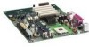
Desktop Board Features CR7F1 OM11834 Figure 3. Location of Standby Power Indicator Power supplies used with this board must be able to provide enough standby current to support the standard Instantly Available (ACPI S3 sleep state) configuration as outlined in Table 4. Values are determined by specifications such as PCI 2.2. Actual measurements may vary. To estimate the total amount of standby current required for a particular system configuration, standby current requirements of all installed components must be added. Refer to the descriptions in Table 4 on page 20 and follow the steps outlined below: 1. Note the total D850MD or D850MV board standby current requirement. 2. Add to that the total PS/2 port standby current requirement if a wake-enabled device is connected. 3. Add, from the PCI 2.2 slots (wake-enabled) row, the total of the number of wake-enabled devices installed (PCI and AGP) multiplied by the standby current requirement. 4. Add, from the PCI 2.2 slots (nonwake-enabled) row, the total of the number of non-wake- enabled devices installed (PCI and AGP) multiplied by the standby current requirement. 5. Add all additional wake-enabled devices' and non-wake-enabled devices' standby current requirements as applicable. 6. Add all the required current totals from steps 1 through 5 to determine the total estimated standby current power supply requirement. 19
-
 1
1 -
2
-
3
-
4
-
5
-
6
-
7
-
8
-
9
-
10
-
11
-
12
-
13
-
 14
14 -
 15
15 -
 16
16 -
 17
17 -
 18
18 -
 19
19 -
 20
20 -
 21
21 -
 22
22 -
 23
23 -
 24
24 -
25
-
26
-
27
-
28
-
29
-
30
-
31
-
32
-
33
-
34
-
35
-
36
-
37
-
38
-
39
-
40
-
41
-
42
-
43
-
44
-
45
-
46
-
47
-
48
-
49
-
50
-
51
-
52
-
53
-
54
-
55
-
56
-
57
-
58
-
59
-
60
-
61
-
62
-
63
-
64
-
65
-
66
-
67
-
68
-
69
-
70
-
71
-
72
-
73
-
74
-
75
-
76
-
77
-
78
-
79
-
80
-
81
-
82
-
83
-
84
-
85
-
86
 |
 |
