Intel D915PDT D915PDT Technical Product Specification - Page 16
System Memory
 |
View all Intel D915PDT manuals
Add to My Manuals
Save this manual to your list of manuals |
Page 16 highlights
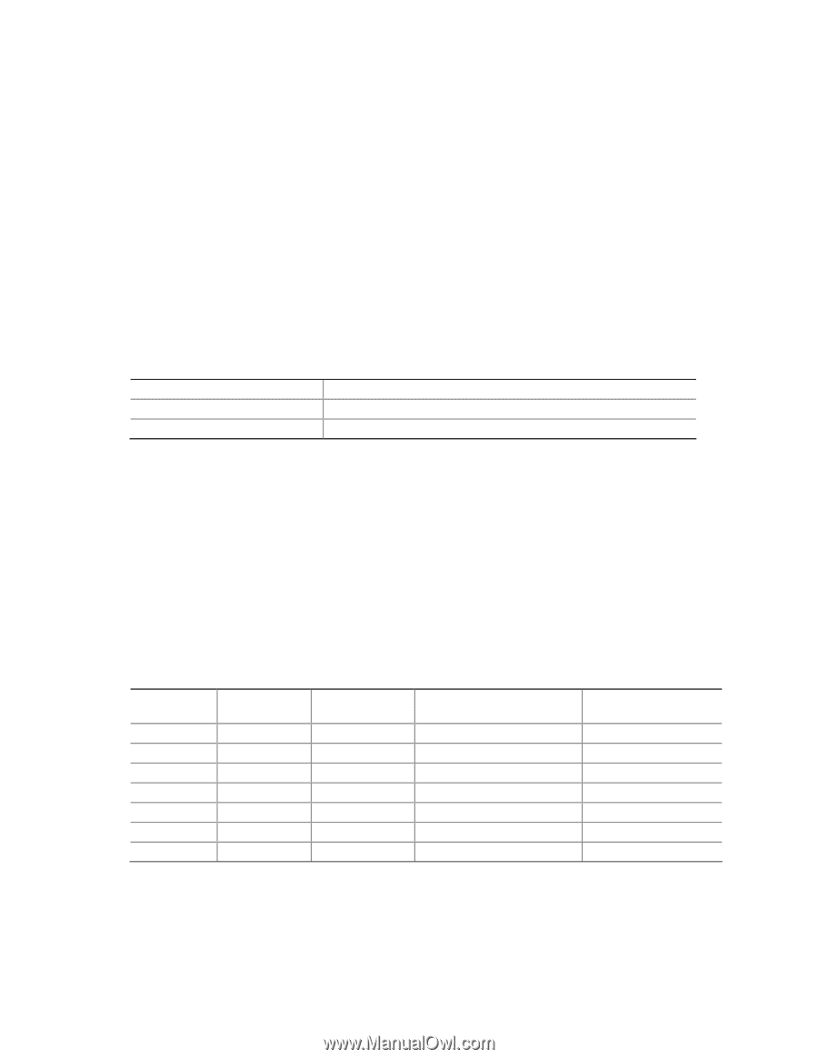
Intel Desktop Board D915PDT Technical Product Specification 1.4 System Memory The board has two DIMM sockets and support the following memory features: • 2.5 V (only) DDR SDRAM DIMMs with gold-plated contacts • Unbuffered, single-sided or double-sided DIMMs with the following restriction: Double-sided DIMMS with x16 organization are not supported. • 2 GB maximum total system memory • Minimum total system memory: 128 MB • Non-ECC DIMMs • Serial Presence Detect • DDR 400 MHz and DDR 333 MHz SDRAM DIMMs Table 3 lists the supported system bus frequency and memory speed combinations. Table 3. Supported System Bus Frequency and Memory Speed Combinations To use this type of DIMM... The processor's system bus frequency must be... DDR 400 DDR 333 (Note) 800 MHz 800 or 533 MHz Note: When using an 800 MHz system bus frequency processor, DDR 333 memory is clocked at 320 MHz. This minimizes system latencies to optimize system throughput. NOTES To be fully compliant with all applicable DDR SDRAM memory specifications, the board should be populated with DIMMs that support the Serial Presence Detect (SPD) data structure. This allows the BIOS to read the SPD data and program the chipset to accurately configure memory settings for optimum performance. If non-SPD memory is installed, the BIOS will attempt to correctly configure the memory settings, but performance and reliability may be impacted or the DIMMs may not function under the determined frequency. Table 4 lists the supported DIMM configurations. Table 4. Supported Memory Configurations DIMM Capacity SDRAM Configuration Density SDRAM Organization Front-side/Back-side Number of SDRAM Devices 128 MB SS 256 Mbit 16 M x 16/empty 4 256 MB SS 256 Mbit 32 M x 8/empty 8 256 MB SS 512 Mbit 32 M x 16/empty 4 512 MB DS 256 Mbit 32 M x 8/32 M x 8 16 512 MB SS 512 Mbit 64 M x 8/empty 8 512 MB SS 1 Gbit 64 M x 16/empty 4 1024 MB SS 1 Gbit 128 M x 8/empty 8 Note: In the second column, "DS" refers to double-sided memory modules (containing two rows of SDRAM) and "SS" refers to single-sided memory modules (containing one row of SDRAM). 16
-
 1
1 -
2
-
3
-
4
-
5
-
6
-
7
-
8
-
9
-
10
-
 11
11 -
 12
12 -
 13
13 -
 14
14 -
 15
15 -
 16
16 -
 17
17 -
 18
18 -
 19
19 -
 20
20 -
 21
21 -
22
-
23
-
24
-
25
-
26
-
27
-
28
-
29
-
30
-
31
-
32
-
33
-
34
-
35
-
36
-
37
-
38
-
39
-
40
-
41
-
42
-
43
-
44
-
45
-
46
-
47
-
48
-
49
-
50
-
51
-
52
-
53
-
54
-
55
-
56
-
57
-
58
-
59
-
60
-
61
-
62
-
63
-
64
-
65
-
66
-
67
-
68
-
69
-
70
-
71
-
72
-
73
-
74
-
75
-
76
-
77
-
78
-
79
-
80
-
81
-
82
-
83
-
84
-
85
-
86
-
87
-
88
 |
 |