Intel D945GBO English Product Guide - Page 7
Inserting a PCI Express x16 Card and Covering the Back Panel VGA Port
 |
View all Intel D945GBO manuals
Add to My Manuals
Save this manual to your list of manuals |
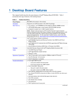
Page 7 highlights
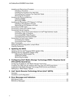
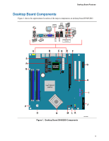
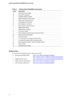
Contents B Regulatory Compliance Safety Regulations ...65 European Union Declaration of Conformity Statement 65 Product Ecology Statements 67 Lead-Free Desktop Board 69 EMC Regulations ...70 Product Certification Markings (Board Level 71 Figures 1. Desktop Board D945GBO Components 11 2. LAN Port LED Locations 16 3. Location of Standby Power Indicator 20 4. Installing the I/O Shield 26 5. Desktop Board D945GBO Mounting Screw Hole Locations 27 6. Lift Socket Lever ...28 7. Lift the Load Plate and Don't Touch the Socket Contacts 28 8. Remove the Protective Socket Cover 29 9. Remove the Processor from the Protective Processor Cover/Do Not Touch 29 10. Install Processor ...30 11. Close the Load Plate ...30 12. Connecting the Processor Fan Heat Sink Cable to the Processor Fan Connector ........31 13. Dual Configuration Example 1 32 14. Dual Configuration Example 2 32 15. Dual Configuration Example 3 33 16. Installing a DIMM ...34 17. Inserting a PCI Express x16 Card and Covering the Back Panel VGA Port 36 18. Connecting the IDE Cable 37 19. Connecting a Serial ATA Cable 38 20. Internal Headers ...39 21. Location of Fan Headers 42 22. Connecting Power Supply Cables 43 23. Location of Other Connectors on Desktop Board D945GBO 44 24. Location of the BIOS Configuration Jumper 45 25. Removing the Battery 51 26. F2 Key ...53 vii
-
 1
1 -
 2
2 -
 3
3 -
 4
4 -
 5
5 -
 6
6 -
 7
7 -
 8
8 -
 9
9 -
 10
10 -
 11
11 -
 12
12 -
13
-
14
-
15
-
16
-
17
-
18
-
19
-
20
-
21
-
22
-
23
-
24
-
25
-
26
-
27
-
28
-
29
-
30
-
31
-
32
-
33
-
34
-
35
-
36
-
37
-
38
-
39
-
40
-
41
-
42
-
43
-
44
-
45
-
46
-
47
-
48
-
49
-
50
-
51
-
52
-
53
-
54
-
55
-
56
-
57
-
58
-
59
-
60
-
61
-
62
-
63
-
64
-
65
-
66
-
67
-
68
-
69
-
70
-
71
-
72
 |
 |
