Intel D945GCL Product Specification - Page 39

Technical Reference - graphics card

Page 39 highlights

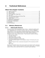
2 Technical Reference What This Chapter Contains 2.1 Memory Resources 39 2.2 DMA Channels 41 2.3 Fixed I/O Map 42 2.4 PCI Configuration Space Map 43 2.5 Interrupts 44 2.6 PCI Conventional Interrupt Routing Map 45 2.7 Connectors and Headers 46 2.8 Jumper Block 56 2.9 Mechanical Considerations 57 2.10 Electrical Considerations 59 2.11 Thermal Considerations 61 2.12 Reliability 63 2.13 Environmental 64 2.1 Memory Resources 2.1.1 Addressable Memory The board utilizes 4 GB of addressable system memory. Typically the address space that is allocated for PCI Conventional bus add-in cards, PCI Express configuration space, BIOS (SPI Flash), and chipset overhead resides above the top of DRAM (total system memory). On a system that has 4 GB of system memory installed, it is not possible to use all of the installed memory due to system address space being allocated for other system critical functions. These functions include the following: • BIOS/ SPI Flash (2 MB) • Local APIC (19 MB) • Digital Media Interface (40 MB) • Front side bus interrupts (17 MB) • PCI Express configuration space (256 MB) • GMCH base address registers, internal graphics ranges, PCI Express ports (up to 512 MB) • Memory-mapped I/O that is dynamically allocated for PCI Conventional and PCI Express add-in cards The amount of installed memory that can be used will vary based on add-in cards and BIOS settings. Figure 11 shows a schematic of the system memory map. All installed system memory can be used when there is no overlap of system addresses. 39

  • 1
  • 2
  • 3
  • 4
  • 5
  • 6
  • 7
  • 8
  • 9
  • 10
  • 11
  • 12
  • 13
  • 14
  • 15
  • 16
  • 17
  • 18
  • 19
  • 20
  • 21
  • 22
  • 23
  • 24
  • 25
  • 26
  • 27
  • 28
  • 29
  • 30
  • 31
  • 32
  • 33
  • 34
  • 35
  • 36
  • 37
  • 38
  • 39
  • 40
  • 41
  • 42
  • 43
  • 44
  • 45
  • 46
  • 47
  • 48
  • 49
  • 50
  • 51
  • 52
  • 53
  • 54
  • 55
  • 56
  • 57
  • 58
  • 59
  • 60
  • 61
  • 62
  • 63
  • 64
  • 65
  • 66
  • 67
  • 68
  • 69
  • 70
  • 71
  • 72
  • 73
  • 74
  • 75
  • 76
  • 77
  • 78
  • 79
  • 80
  • 81
  • 82
  • 83
  • 84
  • 85
  • 86
  • 87
  • 88
  • 89
  • 90

39
2
Technical Reference
What This Chapter Contains
2.1
Memory Resources
..........................................................................
39
2.2
DMA Channels
.................................................................................
41
2.3
Fixed I/O Map
.................................................................................
42
2.4
PCI Configuration Space Map
............................................................
43
2.5
Interrupts
......................................................................................
44
2.6
PCI Conventional Interrupt Routing Map
.............................................
45
2.7
Connectors and Headers
...................................................................
46
2.8
Jumper Block
..................................................................................
56
2.9
Mechanical Considerations
................................................................
57
2.10
Electrical Considerations
...................................................................
59
2.11
Thermal Considerations
....................................................................
61
2.12
Reliability
.......................................................................................
63
2.13
Environmental
................................................................................
64
2.1
Memory Resources
2.1.1
Addressable Memory
The board utilizes 4 GB of addressable system memory.
Typically the address space
that is allocated for PCI Conventional bus add-in cards, PCI Express configuration
space, BIOS (SPI Flash), and chipset overhead resides above the top of DRAM (total
system memory).
On a system that has 4 GB of system memory installed, it is not
possible to use all of the installed memory due to system address space being
allocated for other system critical functions.
These functions include the following:
BIOS/ SPI Flash (2 MB)
Local APIC (19 MB)
Digital Media Interface (40 MB)
Front side bus interrupts (17 MB)
PCI Express configuration space (256 MB)
GMCH base address registers, internal graphics ranges, PCI Express ports (up to
512 MB)
Memory-mapped I/O that is dynamically allocated for PCI Conventional and PCI
Express
add-in cards
The amount of installed memory that can be used will vary based on add-in cards and
BIOS settings.
Figure 11 shows a schematic of the system memory map.
All installed
system memory can be used when there is no overlap of system addresses.