Intel D945GCLF2 Product Guide - Page 31
Connecting the Front Panel Audio Header, Connecting the S/PDIF Connector
 |
UPC - 735858201285
View all Intel D945GCLF2 manuals
Add to My Manuals
Save this manual to your list of manuals |
Page 31 highlights
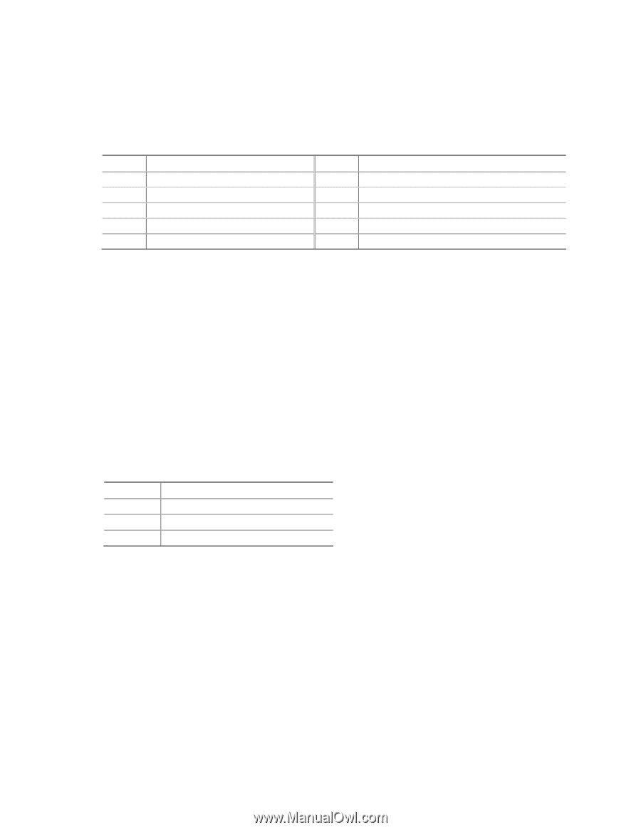
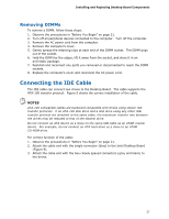
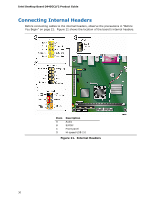
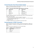
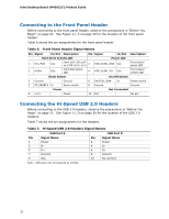
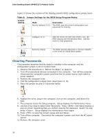
Installing and Replacing Desktop Board Components Connecting the Front Panel Audio Header Figure 11, A shows the location of the front panel audio header. Table 4 shows the pin assignments for the front panel audio header. Table 4. Front Panel Audio Header Signal Names for HD Audio Pin Signal Name 1 PORT 1L 3 PORT 1R 5 PORT 2R 7 SENSE_SEND 9 PORT 2L Pin Signal Name 2 GND 4 PRESENCE# 6 SENSE1_RETURN 8 KEY (no pin) 10 SENSE2_RETURN To install a cable that connects a front panel audio solution to the front panel audio header, follow these steps: 1. Observe the precautions in "Before You Begin" on page 21. 2. Turn off all peripheral devices connected to the computer. Turn off the computer and disconnect the AC power cord. 3. Remove the cover. 4. Install a correctly keyed and shielded front panel audio cable. Connecting the S/PDIF Connector Before connecting to the S/PDIF connector, observe the precautions in "Before You Begin" on page 21. See Figure 11, B on page 30 for the location of the front panel header. Table 5 shows the pin assignments for the front panel header. Table 5. S/PDIF Connector Signal Names Pin Signal Name 1 VCC 2 S/PDIF out 3 Ground 31
-
 1
1 -
2
-
3
-
4
-
5
-
6
-
7
-
8
-
9
-
10
-
11
-
12
-
13
-
14
-
15
-
16
-
17
-
18
-
19
-
20
-
21
-
22
-
23
-
24
-
25
-
 26
26 -
 27
27 -
 28
28 -
 29
29 -
 30
30 -
 31
31 -
 32
32 -
 33
33 -
 34
34 -
 35
35 -
 36
36 -
37
-
38
-
39
-
40
-
41
-
42
-
43
-
44
-
45
-
46
-
47
-
48
-
49
-
50
-
51
-
52
-
53
-
54
-
55
-
56
-
57
-
58
 |
 |