Intel D945GCLF2 Product Guide - Page 7

s, Tables, Intel Desktop Board D945GCLF2 China RoHS Material Self Declaration Table - 10 6 8

Page 7 highlights

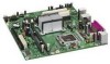
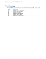
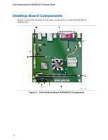
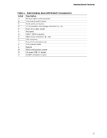
Contents Figures 1. Intel Desktop Board D945GCLF2 Components 10 2. Back Panel Audio Connectors 14 3. LAN Status LEDs 15 4. Location of the Standby Power Indicator 19 5. Installing the I/O Shield 23 6. Intel Desktop Board D945GCLF2 Mounting Screw Holes 24 7. Use DDR2 DIMMs 25 8. Installing a DIMM 26 9. Connecting the IDE Cable 28 10. Connecting the Serial ATA Cable 29 11. Internal Headers 30 12. Location of the Chassis Fan Header 33 13. Connecting a 2 x 10 or 2 x 12 Power Supply Cable 34 14. BIOS Configuration Jumper Block 35 15. Removing the Battery 41 16. Intel Desktop Board D945GCLF2 China RoHS Material Self Declaration Table.........54 Tables 1. Feature Summary 9 2. Intel Desktop Board D945GCLF2 Components 11 3. LAN Status LEDs 15 4. Front Panel Audio Header Signal Names for HD Audio 31 5. S/PDIF Connector Signal Names 31 6. Front Panel Header Signal Names 32 7. Hi-Speed USB 2.0 Headers Signal Names 32 8. Jumper Settings for the BIOS Setup Program Modes 36 9. BIOS Front-panel Power LED Blink Codes 45 10. BIOS Beep Codes 45 11. BIOS Error Messages 46 12. Safety Standards 47 13. Lead-Free Second Level Interconnect Marks 52 14. China RoHS Environmentally Friendly Use Period Mark 53 15. EMC Regulations 55 16. Product Certification Markings 57 vii

  • 1
  • 2
  • 3
  • 4
  • 5
  • 6
  • 7
  • 8
  • 9
  • 10
  • 11
  • 12
  • 13
  • 14
  • 15
  • 16
  • 17
  • 18
  • 19
  • 20
  • 21
  • 22
  • 23
  • 24
  • 25
  • 26
  • 27
  • 28
  • 29
  • 30
  • 31
  • 32
  • 33
  • 34
  • 35
  • 36
  • 37
  • 38
  • 39
  • 40
  • 41
  • 42
  • 43
  • 44
  • 45
  • 46
  • 47
  • 48
  • 49
  • 50
  • 51
  • 52
  • 53
  • 54
  • 55
  • 56
  • 57
  • 58

Contents
vii
Figures
1. Intel Desktop Board D945GCLF2 Components
...................................................
10
2. Back Panel Audio Connectors
.........................................................................
14
3. LAN Status LEDs
..........................................................................................
15
4.
Location of the Standby Power Indicator
..........................................................
19
5. Installing the I/O Shield
................................................................................
23
6.
Intel Desktop Board D945GCLF2 Mounting Screw Holes
.....................................
24
7. Use DDR2 DIMMs
.........................................................................................
25
8. Installing a DIMM
.........................................................................................
26
9. Connecting the IDE Cable
..............................................................................
28
10. Connecting the Serial ATA Cable
.....................................................................
29
11. Internal Headers
..........................................................................................
30
12. Location of the Chassis Fan Header
.................................................................
33
13. Connecting a 2 x 10 or 2 x 12 Power Supply Cable
............................................
34
14. BIOS Configuration Jumper Block
....................................................................
35
15. Removing the Battery
...................................................................................
41
16. Intel Desktop Board D945GCLF2 China RoHS Material Self Declaration Table
.........
54
Tables
1.
Feature Summary
..........................................................................................
9
2.
Intel Desktop Board D945GCLF2 Components
...................................................
11
3.
LAN Status LEDs
..........................................................................................
15
4.
Front Panel Audio Header Signal Names for HD Audio
........................................
31
5.
S/PDIF Connector Signal Names
.....................................................................
31
6.
Front Panel Header Signal Names
...................................................................
32
7.
Hi-Speed USB 2.0 Headers Signal Names
.........................................................
32
8.
Jumper Settings for the BIOS Setup Program Modes
..........................................
36
9.
BIOS Front-panel Power LED Blink Codes
.........................................................
45
10.
BIOS Beep Codes
.........................................................................................
45
11.
BIOS Error Messages
....................................................................................
46
12.
Safety Standards
..........................................................................................
47
13.
Lead-Free Second Level Interconnect Marks
.....................................................
52
14.
China RoHS Environmentally Friendly Use Period Mark
.......................................
53
15.
EMC Regulations
...........................................................................................
55
16.
Product Certification Markings
........................................................................
57