Intel D955XBK Product Specification - Page 35
Thermal Monitoring
 |
View all Intel D955XBK manuals
Add to My Manuals
Save this manual to your list of manuals |
Page 35 highlights
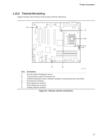
1.13.2 Thermal Monitoring Figure 14 shows the location of the sensors and fan connectors. 4 G 1 3 1 Product Description A B C 4 1 D 31 F E OM17725 Item A B C D E F G Description Remote ambient temperature sensor Thermal diode, located on processor die Ambient temperature sensor, internal to hardware monitoring and fan control ASIC Processor fan connector Rear chassis fan connector Front chassis fan connector Auxiliary rear fan connector Figure 14. Sensors and Fan Connectors 35
-
 1
1 -
2
-
3
-
4
-
5
-
6
-
7
-
8
-
9
-
10
-
11
-
12
-
13
-
14
-
15
-
16
-
17
-
18
-
19
-
20
-
21
-
22
-
23
-
24
-
25
-
26
-
27
-
28
-
29
-
 30
30 -
 31
31 -
 32
32 -
 33
33 -
 34
34 -
 35
35 -
 36
36 -
 37
37 -
 38
38 -
 39
39 -
 40
40 -
41
-
42
-
43
-
44
-
45
-
46
-
47
-
48
-
49
-
50
-
51
-
52
-
53
-
54
-
55
-
56
-
57
-
58
-
59
-
60
-
61
-
62
-
63
-
64
-
65
-
66
-
67
-
68
-
69
-
70
-
71
-
72
-
73
-
74
-
75
-
76
-
77
-
78
-
79
-
80
-
81
-
82
-
83
-
84
-
85
-
86
-
87
-
88
-
89
-
90
-
91
-
92
-
93
-
94
 |
 |

Product Description
35
1.13.2
Thermal Monitoring
Figure 14 shows the location of the sensors and fan connectors.
OM17725
D
A
C
E
F
G
B
1
4
1
3
3
1
1
4
Item
Description
A
Remote ambient temperature sensor
B
Thermal diode, located on processor die
C
Ambient temperature sensor, internal to hardware monitoring and fan control ASIC
D
Processor fan connector
E
Rear chassis fan connector
F
Front chassis fan connector
G
Auxiliary rear fan connector
Figure 14.
Sensors and Fan Connectors