Intel DC3217BY Technical Product Specification - Page 10

Tables - desktop computer

Page 10 highlights

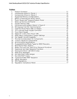
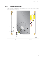
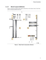
Intel Desktop Board D33217CK Technical Product Specification Tables 1. Feature Summary 11 2. Components Shown in Figure 1 14 3. Components Shown in Figure 2 16 4. Supported Memory Configurations 19 5. Effects of Pressing the Power Switch 27 6. Power States and Targeted System Power 28 7. Wake-up Devices and Events 29 8. System Memory Map 35 9. Connectors and Headers Shown in Figure 9 38 10. PCI Express Full-Mini Card Connector 39 11. Dual-Port Front Panel USB 2.0 Header 40 12. 19 V Internal Power Supply Connector 41 13. Front Panel Header 41 14. States for a One-Color Power LED 42 15. BIOS Setup Configuration Jumper Settings 45 16. Fan Header Current Capability 48 17. Thermal Considerations for Components 50 18. Tcontrol Values for Components 50 19. Environmental Specifications 51 20. AcceptableDrives/Media Types for BIOS Recovery 56 21. Boot Device Menu Options 57 22. Master Key and User Hard Drive Password Functions 58 23. Supervisor and User Password Functions 59 24. Front-panel Power LED Blink Codes 61 25. BIOS Error Messages 61 26. Port 80h POST Code Ranges 62 27. Port 80h POST Codes 63 28. Typical Port 80h POST Sequence 67 29. Safety Standards 69 30. EMC Regulations 73 31. Regulatory Compliance Marks 77 x

  • 1
  • 2
  • 3
  • 4
  • 5
  • 6
  • 7
  • 8
  • 9
  • 10
  • 11
  • 12
  • 13
  • 14
  • 15
  • 16
  • 17
  • 18
  • 19
  • 20
  • 21
  • 22
  • 23
  • 24
  • 25
  • 26
  • 27
  • 28
  • 29
  • 30
  • 31
  • 32
  • 33
  • 34
  • 35
  • 36
  • 37
  • 38
  • 39
  • 40
  • 41
  • 42
  • 43
  • 44
  • 45
  • 46
  • 47
  • 48
  • 49
  • 50
  • 51
  • 52
  • 53
  • 54
  • 55
  • 56
  • 57
  • 58
  • 59
  • 60
  • 61
  • 62
  • 63
  • 64
  • 65
  • 66
  • 67
  • 68
  • 69
  • 70
  • 71
  • 72
  • 73
  • 74
  • 75
  • 76
  • 77
  • 78
  • 79
  • 80
  • 81
  • 82

Intel Desktop Board D33217CK Technical Product Specification
x
Tables
1.
Feature Summary
.............................................................................
11
2.
Components Shown in Figure 1
..........................................................
14
3.
Components Shown in Figure 2
..........................................................
16
4.
Supported Memory Configurations
......................................................
19
5.
Effects of Pressing the Power Switch
...................................................
27
6.
Power States and Targeted System Power
...........................................
28
7.
Wake-up Devices and Events
.............................................................
29
8.
System Memory Map
........................................................................
35
9.
Connectors and Headers Shown in Figure 9
.........................................
38
10. PCI Express Full-Mini Card Connector
..................................................
39
11. Dual-Port Front Panel USB 2.0 Header
.................................................
40
12. 19 V Internal Power Supply Connector
................................................
41
13. Front Panel Header
...........................................................................
41
14. States for a One-Color Power LED
.......................................................
42
15. BIOS Setup Configuration Jumper Settings
..........................................
45
16. Fan Header Current Capability
............................................................
48
17. Thermal Considerations for Components
..............................................
50
18. Tcontrol Values for Components
.........................................................
50
19. Environmental Specifications
..............................................................
51
20. AcceptableDrives/Media Types for BIOS Recovery
.................................
56
21. Boot Device Menu Options
.................................................................
57
22. Master Key and User Hard Drive Password Functions
............................
58
23. Supervisor and User Password Functions
.............................................
59
24. Front-panel Power LED Blink Codes
.....................................................
61
25. BIOS Error Messages
........................................................................
61
26. Port 80h POST Code Ranges
..............................................................
62
27. Port 80h POST Codes
........................................................................
63
28. Typical Port 80h POST Sequence
........................................................
67
29. Safety Standards
..............................................................................
69
30. EMC Regulations
...............................................................................
73
31. Regulatory Compliance Marks
............................................................
77