Intel DH55HC Product Guide - Page 49
Chassis Intrusion Header, Intel® RPAT Header, Alternate Front Panel Power LED Header
 |
View all Intel DH55HC manuals
Add to My Manuals
Save this manual to your list of manuals |
Page 49 highlights
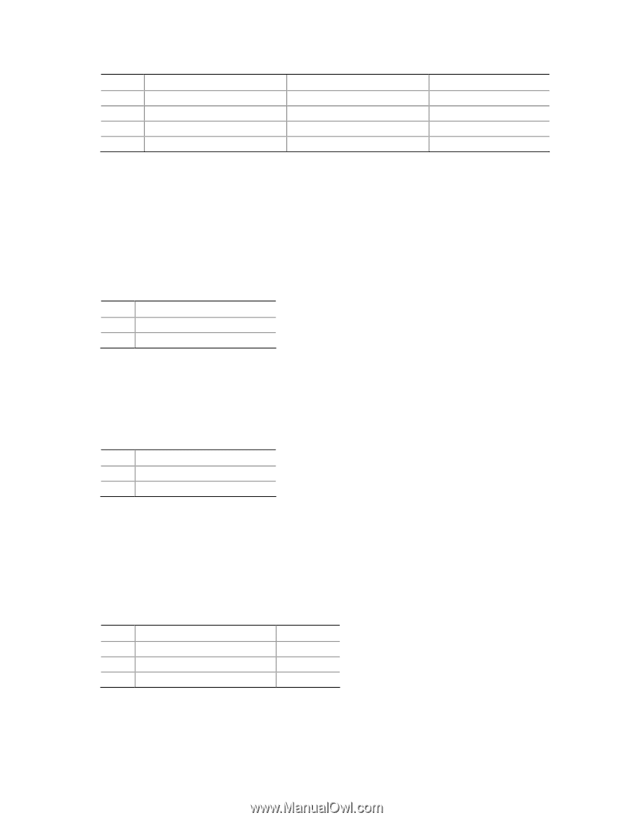
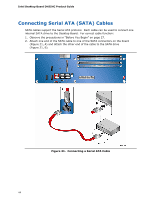
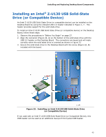
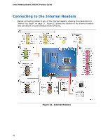
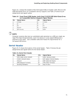
Installing and Replacing Desktop Board Components Pin Standard Signal Name ECP Signal Name 23 PERROR PE, ACKREVERSE# 24 GROUND GROUND 25 SELECT SELECT 26 KEY (no pin) KEY (no pin) EPP Signal Name PE GROUND SELECT KEY (no pin) Chassis Intrusion Header Figure 23, E shows the location of the chassis intrusion header. This header can be connected to a mechanical switch on the chassis to detect if the chassis cover is removed. This switch should be in the open position when the chassis cover is installed and closed when the cover is removed. Table 9 shows the pin assignments and signal names for the chassis intrusion header. Table 9. Chassis Intrusion Header Signal Names Pin Description 1 Intruder# 2 Ground Intel® RPAT Header Figure 23, F shows the location of the Intel RPAT header. Table 10 shows the pin assignments and signal names for the Intel RPAT header. Table 10. Intel RPAT Header Signal Names Pin Description 1 RPAT# 2 Ground Alternate Front Panel Power LED Header Figure 23, G shows the location of the alternate front panel power LED header. Pins 1 and 3 of this header duplicate the signals on pins 2 and 4 of the front panel header. If your chassis has a three-pin power LED cable, connect it to this header. Table 11 shows the pin assignments for the alternate front panel header. Table 11. Alternate Front Panel Power LED Header Signal Names Pin Signal Name 1 Front panel LED+ 2 No pin 3 Front panel LED- In/Out Out Out 49
-
 1
1 -
2
-
3
-
4
-
5
-
6
-
7
-
8
-
9
-
10
-
11
-
12
-
13
-
14
-
15
-
16
-
17
-
18
-
19
-
20
-
21
-
22
-
23
-
24
-
25
-
26
-
27
-
28
-
29
-
30
-
31
-
32
-
33
-
34
-
35
-
36
-
37
-
38
-
39
-
40
-
41
-
42
-
43
-
 44
44 -
 45
45 -
 46
46 -
 47
47 -
 48
48 -
 49
49 -
 50
50 -
 51
51 -
 52
52 -
 53
53 -
 54
54 -
55
-
56
-
57
-
58
-
59
-
60
-
61
-
62
-
63
-
64
-
65
-
66
-
67
-
68
-
69
-
70
-
71
-
72
-
73
-
74
-
75
-
76
-
77
-
78
-
79
-
80
-
81
-
82
 |
 |