Intel DH55HC Product Guide - Page 51
Serial Header, Table 14. Front Panel USB Header with Intel Z-U130 USB Solid-State Drive
 |
View all Intel DH55HC manuals
Add to My Manuals
Save this manual to your list of manuals |
Page 51 highlights
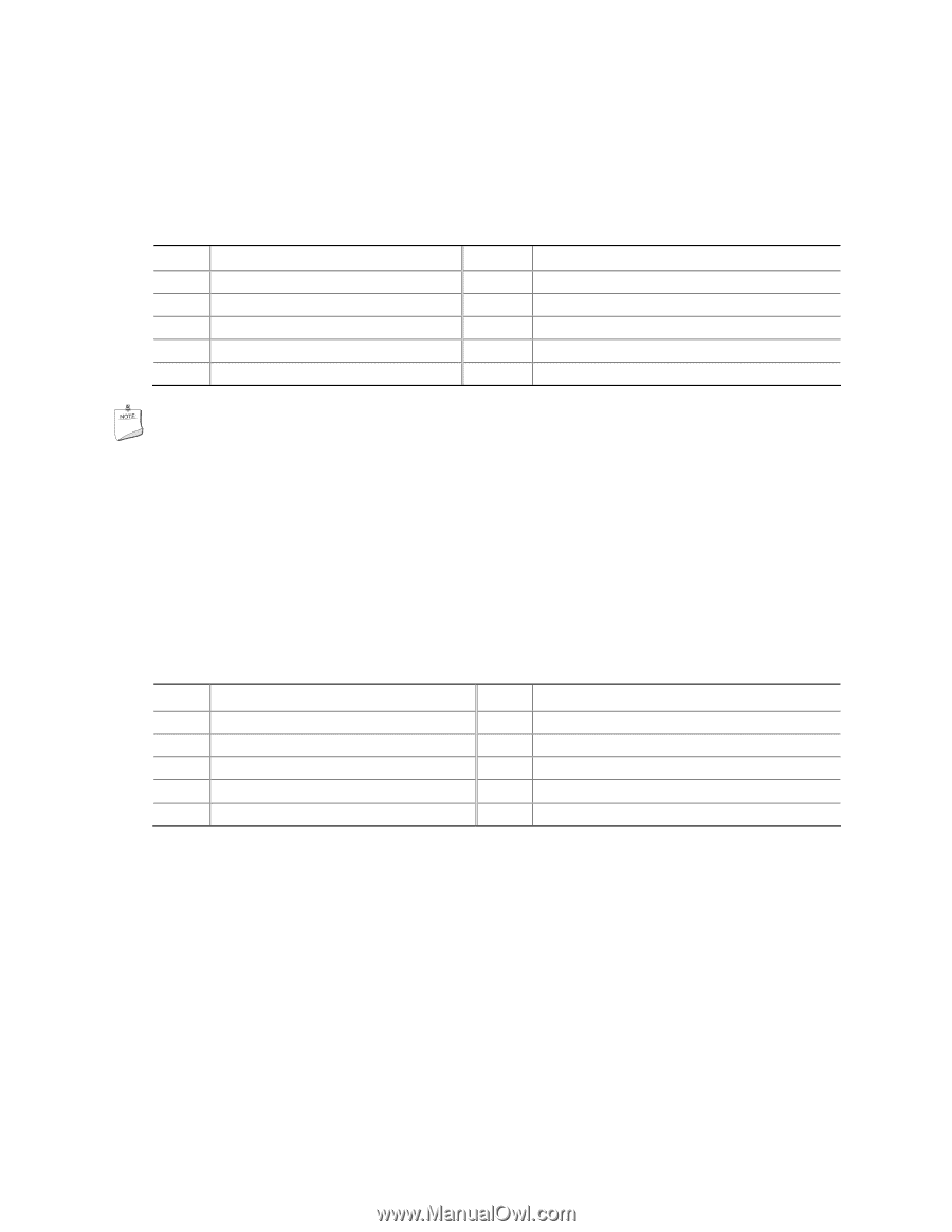
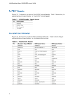
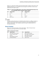
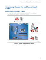
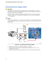
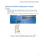
Installing and Replacing Desktop Board Components Figure 23, J shows the location of the front panel USB 2.0 header (with Intel Z-U130 USB Solid-State Drive (or Compatible Device) Support) and Table 14 shows its pin assignments and signal names. Table 14. Front Panel USB Header (with Intel Z-U130 USB Solid-State Drive (or Compatible Device) Support) Signal Names Pin Signal Name 1 +5 VDC 3 D- 5 D+ 7 Ground 9 KEY (no pin) Pin Signal Name 2 +5 VDC 4 D- 6 D+ 8 Ground 10 LED# NOTE Computer systems that have an unshielded cable attached to a USB port might not meet FCC Class B requirements, even if no device or a low-speed USB device is attached to the cable. Use a shielded cable that meets the requirements for a full-speed USB device. Serial Header Figure 23, K shows the location of the serial header. Table 15 shows the pin assignments and signal names for the serial header. Table 15. Serial Port Header Pin Signal Name 1 DCD (Data Carrier Detect) 3 TXD# (Transmit Data) 5 Ground 7 RTS (Request To Send) 9 RI (Ring Indicator) Pin Signal Name 2 RXD# (Receive Data) 4 DTR (Data Terminal Ready) 6 DSR (Data Set Ready) 8 CTS (Clear To Send) 10 Key (no pin) 51
-
 1
1 -
2
-
3
-
4
-
5
-
6
-
7
-
8
-
9
-
10
-
11
-
12
-
13
-
14
-
15
-
16
-
17
-
18
-
19
-
20
-
21
-
22
-
23
-
24
-
25
-
26
-
27
-
28
-
29
-
30
-
31
-
32
-
33
-
34
-
35
-
36
-
37
-
38
-
39
-
40
-
41
-
42
-
43
-
44
-
45
-
 46
46 -
 47
47 -
 48
48 -
 49
49 -
 50
50 -
 51
51 -
 52
52 -
 53
53 -
 54
54 -
 55
55 -
 56
56 -
57
-
58
-
59
-
60
-
61
-
62
-
63
-
64
-
65
-
66
-
67
-
68
-
69
-
70
-
71
-
72
-
73
-
74
-
75
-
76
-
77
-
78
-
79
-
80
-
81
-
82
 |
 |