Intel DH61DL English Product Guide - Page 46
S/PDIF Header, Connecting to the Audio System
 |
View all Intel DH61DL manuals
Add to My Manuals
Save this manual to your list of manuals |
Page 46 highlights
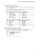
Intel Desktop Board DH61DL Product Guide S/PDIF Header Figure 19, H shows the location of the S/PDIF output header. Table 12 shows the pin assignments and signal names for the S/PDIF output header. Table 12. S/PDIF Header Signal Names Pin Description 1 Ground 2 S/PDIF Out 3 Key (no pin) 4 +5 VDC Connecting to the Audio System After installing the Realtek audio driver from the Intel® Express Installer DVD-ROM, the multi-channel audio feature can be enabled. Figure 20 shows the back panel audio connectors. The default connector assignments are shown in the table. Item Description A Line in B Line out (front speaker/headphones) C Mic in Figure 20. Back Panel Audio Connectors NOTE The back panel line out connector is designed to power either headphones or amplified speakers only. Poor audio quality may occur if passive (non-amplified) speakers are connected to this output. 46
-
 1
1 -
2
-
3
-
4
-
5
-
6
-
7
-
8
-
9
-
10
-
11
-
12
-
13
-
14
-
15
-
16
-
17
-
18
-
19
-
20
-
21
-
22
-
23
-
24
-
25
-
26
-
27
-
28
-
29
-
30
-
31
-
32
-
33
-
34
-
35
-
36
-
37
-
38
-
39
-
40
-
 41
41 -
 42
42 -
 43
43 -
 44
44 -
 45
45 -
 46
46 -
 47
47 -
 48
48 -
 49
49 -
 50
50 -
 51
51 -
52
-
53
-
54
-
55
-
56
-
57
-
58
-
59
-
60
-
61
-
62
-
63
-
64
-
65
-
66
-
67
-
68
-
69
-
70
-
71
-
72
-
73
-
74
-
75
-
76
 |
 |
