Intel DH67BL Product Guide - Page 36
Installing and Removing System Memory, Guidelines for Dual Channel Memory Configuration
 |
View all Intel DH67BL manuals
Add to My Manuals
Save this manual to your list of manuals |
Page 36 highlights
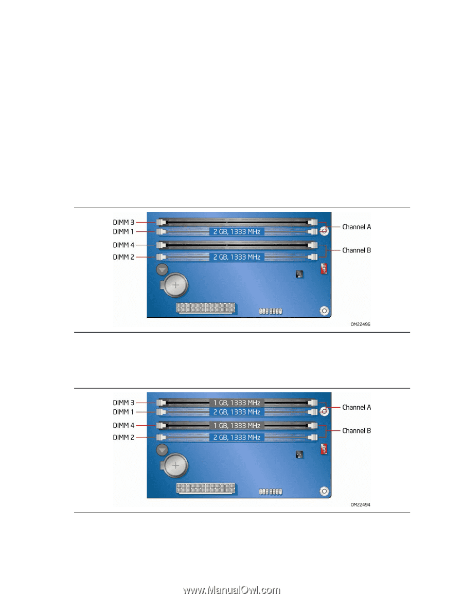
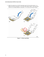
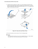
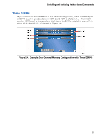
Intel Desktop Board DH67BL Product Guide Installing and Removing System Memory Desktop board DH67BL has four 240-pin DDR3 DIMM sockets arranged in two channels (A and B). Guidelines for Dual Channel Memory Configuration Before installing DIMMs, read and follow these guidelines for dual channel memory configuration. Two or Four DIMMs Install a matched pair of DIMMs equal in speed and size (see Figure 12) in the blue socket of channel A (DIMM 1) and channel B (DIMM 2). Figure 12. Example Dual Channel Memory Configuration with Two DIMMs If additional memory is to be used, install another matched pair of DIMMs (see Figure 13) in the black socket of channel A (DIMM 3) and channel B (DIMM 4). Figure 13. Example Dual Channel Memory Configuration with Four DIMMs 36
-
 1
1 -
2
-
3
-
4
-
5
-
6
-
7
-
8
-
9
-
10
-
11
-
12
-
13
-
14
-
15
-
16
-
17
-
18
-
19
-
20
-
21
-
22
-
23
-
24
-
25
-
26
-
27
-
28
-
29
-
30
-
 31
31 -
 32
32 -
 33
33 -
 34
34 -
 35
35 -
 36
36 -
 37
37 -
 38
38 -
 39
39 -
 40
40 -
 41
41 -
42
-
43
-
44
-
45
-
46
-
47
-
48
-
49
-
50
-
51
-
52
-
53
-
54
-
55
-
56
-
57
-
58
-
59
-
60
-
61
-
62
-
63
-
64
-
65
-
66
-
67
-
68
-
69
-
70
-
71
-
72
-
73
-
74
-
75
-
76
-
77
-
78
 |
 |