Intel DP55KG Product Guide
Intel DP55KG - Desktop Board Extreme Series Motherboard Manual
 |
UPC - 735858205979
View all Intel DP55KG manuals
Add to My Manuals
Save this manual to your list of manuals |
Intel DP55KG manual content summary:
- Intel DP55KG | Product Guide - Page 1
Intel® Desktop Board DP55KG Product Guide Order Number: E62884-003 - Intel DP55KG | Product Guide - Page 2
Revision -001 -002 -003 Revision History First release of the Intel® Desktop Board DP55KG Product Guide Second release of the Intel® Desktop Board DP55KG Product Guide Third release of the Intel® Desktop Board DP55KG Product Guide Date July 2009 December 2009 April 2010 If an FCC declaration of - Intel DP55KG | Product Guide - Page 3
Board and other hardware components 3 Updating the BIOS: instructions on how to update the BIOS 4 Configuring for RAID Using Intel® Matrix Storage Technology: information about configuring your system for RAID A Error Messages and Indicators: information about BIOS error messages and beep codes - Intel DP55KG | Product Guide - Page 4
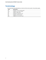
Intel Desktop Board DP55KG Product Guide Terminology The table below gives descriptions of some common terms used in the product guide. Term Description GB Gigabyte (1,073,741,824 bytes) GHz Gigahertz (one billion hertz) KB Kilobyte (1024 bytes) MB Megabyte (1,048,576 bytes) Mb Megabit - Intel DP55KG | Product Guide - Page 5
Board Features Supported Operating Systems 11 Desktop Board Components 12 Processor ...14 Main Memory...15 Intel® P55 Express Chipset 16 Audio Subsystem 16 LAN Subsystem 16 Bluetooth* Technology Support 17 USB 2.0 Support 17 Serial ATA Support 18 Legacy I/O ...19 Expandability...19 BIOS - Intel DP55KG | Product Guide - Page 6
Intel Desktop Board DP55KG Product Guide Installing the I/O Shield 33 Installing and Removing the Desktop Board 34 Installing and Removing a Processor 35 Installing a Processor 35 Installing the Processor Fan Heat Sink 40 Connecting the Processor Fan Heat Sink Cable 40 Removing the Processor - Intel DP55KG | Product Guide - Page 7
12 2. LAN Connector LEDs 17 3. SATA Drive Activity LED 18 4. Location of the Standby Power Indicator 24 5. Onboard Power Button 26 6. Location of the Processor and Voltage Regulator LEDs 27 7. Location of the Back to BIOS Button 28 8. Installing the I/O Shield 33 9. Intel Desktop Board DP55KG - Intel DP55KG | Product Guide - Page 8
the Chassis Fan Headers 56 30. Connecting Power Supply Cables 57 31. Connecting the Bluetooth Antenna 58 32. Location of the BIOS Configuration Jumper Block 59 33. Removing the Battery 66 34. POST Code LED Display 75 35. Intel Desktop Board DP55KG China RoHS Material Self Declaration Table 87 - Intel DP55KG | Product Guide - Page 9
Intel® Desktop Board DP55KG. Table 1 summarizes the major features of the Desktop Board. Table 1. Feature Summary Form Factor Processor Main Memory ATX (304.80 millimeters [12.00 inches] x 243.84 millimeters [9.60 inches]) Support for an Intel® processor in the LGA1156 package • Four 240-pin DDR3 - Intel DP55KG | Product Guide - Page 10
Desktop Board DP55KG Product Guide Table 1. Feature Summary (continued) RAID Intel® Matrix Storage Technology for Serial ATA LAN Support Intel 82578DM Gigabit (10/100/1000 Mb/s) Ethernet LAN controller including an RJ-45 back panel connector with integrated status LEDs Wireless Support BIOS - Intel DP55KG | Product Guide - Page 11
Desktop Board Features Supported Operating Systems The Desktop Board supports the following operating systems: • Microsoft Windows* 7 Ultimate 64-bit edition • Microsoft Windows 7 Ultimate 32-bit edition • Microsoft Windows 7 Home Basic 64-bit edition • Microsoft Windows 7 Home Basic 32-bit edition - Intel DP55KG | Product Guide - Page 12
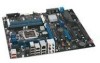
Intel Desktop Board DP55KG Product Guide Desktop Board Components Figure 1 shows the approximate location of the major components on Intel Desktop Board DP55KG. Figure 1. Intel Desktop Board DP55KG Components 12 - Intel DP55KG | Product Guide - Page 13
USB connector 12 V processor core voltage connector (2 x 4 pin) Processor fan header Processor LED Voltage regulator LED Processor socket POST code LED display DDR3 Channel A, DIMM 0 and DIMM 1 sockets DDR3 Channel B, DIMM 0 and DIMM 1 sockets Onboard power button Standby power indicator LED Main - Intel DP55KG | Product Guide - Page 14
for Intel Desktop Board DP55KG http://www.intel.com/products/motherboard/DP55KG /index.htm • Supported processors http://processormatch.intel.com • Chipset information http://www.intel.com/products/desktop/chipsets/inde x.htm • BIOS and driver updates http://downloadcenter.intel.com - Intel DP55KG | Product Guide - Page 15
arranged in two channels • 1600+/1333/1066 MHz DDR3 SDRAM Memory Modules NOTE DDR3 1600 or higher memory support on this desktop board requires compatible XMP-enabled memory or advanced knowledge of BIOS and manual memory tuning. Individual results may vary. • Support for single- and dual-channel - Intel DP55KG | Product Guide - Page 16
Intel Desktop Board DP55KG Product Guide Intel® P55 Express Chipset The Intel P55 Express Chipset consists of the Intel P55 Platform Controller Hub (PCH). The PCH is the centralized controller for the board's I/O paths. Audio Subsystem The onboard audio subsystem consists of the following components - Intel DP55KG | Product Guide - Page 17
Driver support is provided by Microsoft operating systems such as Microsoft Windows Vista and the Microsoft Windows 7. Refer to Connecting the Bluetooth Antenna on page 58 for information on how to connect the antenna provided with the board to the Bluetooth module. USB 2.0 Support The Desktop Board - Intel DP55KG | Product Guide - Page 18
Intel Desktop Board DP55KG Product Guide Serial ATA Support Intel Desktop Board DP55KG supports eight onboard 3.0 Gb/s Serial ATA (SATA) channels (six via the PCH and two via a discrete SATA controller). The board also provides two backpanel 3.0 Gb/s external SATA (eSATA) channels via the discrete - Intel DP55KG | Product Guide - Page 19
Desktop Board Features NOTE In order to use supported onboard RAID features, you must first enable RAID in the BIOS. Also, during Microsoft Windows XP installation, you must press the F6 key to install the RAID drivers. Refer to your Microsoft Windows XP documentation for more information about - Intel DP55KG | Product Guide - Page 20
Intel Desktop Board DP55KG Product Guide BIOS The BIOS provides the Power-On Self-Test (POST), the BIOS Setup program, and the PCI/PCI Express and SATA auto-configuration utilities. The BIOS is stored in the Serial Peripheral Interface (SPI) Flash device. The BIOS can be updated by following the - Intel DP55KG | Product Guide - Page 21
features of Intel Desktop Board DP55KG enable the board to be compatible with the Wired for Management (WfM) specification. The board has several control include: • Monitoring of power supply voltages to detect levels above and below acceptable values • Intel® Precision Cooling Technology fan speed - Intel DP55KG | Product Guide - Page 22
Intel Desktop Board DP55KG Product Guide Power Management Power management is implemented at several levels, including software support through the Advanced Configuration and Power Interface (ACPI) and the following hardware support: • Power connectors • Fan headers • LAN wake capabilities • - Intel DP55KG | Product Guide - Page 23
) configuration. If the standby current necessary to support multiple wake events from the PCI and/or USB buses exceeds power supply capacity, the Desktop Board may lose register settings stored in memory. Instantly Available PC technology enables the board to enter the ACPI S3 (Suspend-toRAM) sleep - Intel DP55KG | Product Guide - Page 24
present at the memory module sockets and the PCI bus connectors. Figure 4. Location of the Standby Power Indicator For more information on standby current requirements for the Desktop Board, refer to the Technical Product Specification at http://support.intel.com/support/motherboards/desktop/ 24 - Intel DP55KG | Product Guide - Page 25
wakes from an ACPI S1, S3, S4, or S5 state. WAKE# Signal Wake-up Support When the WAKE# signal on the PCI Express bus is asserted, the computer wakes from an recommended configurations, go to http://www.intel.com/go/energystar. The Desktop Board also meets the following international requirements: - Intel DP55KG | Product Guide - Page 26
Intel Desktop Board DP55KG Product Guide Onboard Power Button CAUTION Electrostatic discharge (ESD) can damage antistatic wrist strap and attaching it to a metal part of the computer chassis. The power button on the Desktop Board (see Figure 5) can be used to turn the computer on or off. This button - Intel DP55KG | Product Guide - Page 27
Desktop Board Features Processor and Voltage Regulator LEDs The Desktop Board contains two red LEDs (see Figure 6) that indicate the status of the board's voltage regulation circuitry and the processor: • The Processor LED (Figure 6, A) indicates an elevated temperature on the processor that could - Intel DP55KG | Product Guide - Page 28
Intel Desktop Board DP55KG Product Guide Back to BIOS Button The Back to BIOS button (Figure 7, A) duplicates the functionality of the BIOS configuration jumper (see Setting the BIOS Configuration Jumper on page 59) with the following exceptions: • It can only be used to force the board to power on - Intel DP55KG | Product Guide - Page 29
is mounted on the Desktop Board. The speaker provides audible error code (beep code) information during the Power-On Self-Test (POST). Refer to Appendix A for a description of the board's beep codes. Battery A battery on the Desktop Board keeps the values in CMOS RAM and the clock current when - Intel DP55KG | Product Guide - Page 30
Intel Desktop Board DP55KG Product Guide 30 - Intel DP55KG | Product Guide - Page 31
the Desktop Board • Install and remove a processor • Install and remove memory • Install and remove a PCI Express x16 graphics card • Connect the Serial ATA cables • Connect to the internal headers • Connect to the audio system • Connect chassis fan and power supply cables • Connect the Bluetooth - Intel DP55KG | Product Guide - Page 32
Intel Desktop Board DP55KG Product Guide Installation Precautions When you install and test the Intel Desktop Board, observe all warnings and cautions in the installation instructions. To avoid injury, be careful of: • Sharp pins on connectors • Sharp pins on printed circuit assemblies • Rough edges - Intel DP55KG | Product Guide - Page 33
components from dust and foreign objects, and promotes correct airflow within the chassis. Install the I/O shield before installing the Desktop Board in the chassis. Place the shield inside the chassis as shown in Figure 8. Press the shield into place so that it fits tightly and securely. If the - Intel DP55KG | Product Guide - Page 34
the power before you open the computer can result in personal injury or equipment damage. Refer to your chassis manual for instructions on installing and removing the Desktop Board. Figure 9 shows the location of the mounting screw holes for Intel Desktop Board DP55KG. Figure 9. Intel Desktop Board - Intel DP55KG | Product Guide - Page 35
and Replacing Desktop Board Components Installing and Removing a Processor Instructions on how to install the processor on the Desktop Board are given below. Installing a Processor CAUTION Before installing or removing a processor, make sure the AC power has been removed by unplugging the power cord - Intel DP55KG | Product Guide - Page 36
Intel Desktop Board DP55KG Product Guide 3. Rotate the socket lever to lift the load plate away from the socket (Figure 11, A). Make sure that the load plate is in the fully open position (Figure 11, B) while being careful not to damage adjacent components. Figure 11. Lift the Load Plate 36 - Intel DP55KG | Product Guide - Page 37
Installing and Replacing Desktop Board Components 4. Remove the protective socket cover from the socket by placing your thumb against the front cover; save it for possible future use. Always replace the socket cover if you remove the processor from the socket. Figure 12. Remove the Socket Cover 37 - Intel DP55KG | Product Guide - Page 38
Intel Desktop Board DP55KG Product Guide 5. Remove the processor from its protective cover. Hold the processor only at the edges, being careful not to touch the bottom of the processor (see Figure 13). NOTE Do not discard the processor cover. Always replace the processor cover if you remove the - Intel DP55KG | Product Guide - Page 39
Installing and Replacing Desktop Board Components 7. Lower the load plate over the processor while leaving the socket lever in the open position (Figure 15). Figure 15. Lower the Load Plate 8. Lower the socket lever (Figure 16, B) while making - Intel DP55KG | Product Guide - Page 40
Intel Desktop Board DP55KG Product Guide Installing the Processor Fan Heat Sink Intel Desktop Board DP55KG has mounting holes for a processor fan heat sink. For instructions on how to attach the processor fan heat sink to the Desktop Board, refer to the boxed processor manual or boxed thermal - Intel DP55KG | Product Guide - Page 41
and Replacing Desktop Board Components Installing and Removing System Memory Desktop board DP55KG has four 240-pin DDR3 DIMM sockets arranged as DIMM 0 and DIMM 1 in both Channel A and Channel B. NOTE The Intel P55 Express Chipset requires memory to be installed in the Channel A, DIMM 0 slot - Intel DP55KG | Product Guide - Page 42
Intel Desktop Board DP55KG Product Guide If additional memory is to be used, install another matched pair of DIMMs in DIMM 1 (black) in channels A and B (see Figure 19). Figure 19. Example Dual Channel Memory Configuration with Four DIMMs Three DIMMs If you want to use three DIMMs in a dual-channel - Intel DP55KG | Product Guide - Page 43
Installing and Replacing Desktop Board Components Installing DIMMs To make sure you have the correct DIMM, place it on the illustration of the DDR3 DIMM in Figure 21. All the notches should match with the DDR3 DIMM. Figure 21. Use DDR3 DIMMs 43 - Intel DP55KG | Product Guide - Page 44
Intel Desktop Board DP55KG Product Guide NOTE For best memory performance, install memory in the blue DIMM sockets first. To install a DIMM, follow these steps: 1. Observe the precautions in "Before You Begin" on page 31. 2. Turn off all peripheral devices connected to the computer. Turn off - Intel DP55KG | Product Guide - Page 45
the PCI Express graphics card (see Installing a PCI Express x16 Graphics Card on power on the system. If the card is not fully seated in the connector, an electrical short may result across the connector pins. Depending on the over-current protection of the power supply, certain Desktop Board - Intel DP55KG | Product Guide - Page 46
Intel Desktop Board DP55KG Product Guide Follow these instructions to install a PCI Express x16 graphics card: 1. Observe the precautions in "Before You Begin" on page 31. 2. Place the card in the PCI Express x16 connector (Figure - Intel DP55KG | Product Guide - Page 47
Graphics Cards The Desktop Board supports technology that allows you to install linked PCI Express graphics cards such as NVIDIA* SLI* (Scalable Link Interface) cards. Make sure you use two identical SLI-ready graphics cards that are NVIDIA certified and the latest graphics driver. You can use - Intel DP55KG | Product Guide - Page 48
Intel Desktop Board DP55KG Product Guide To install two linked PCI Express graphics cards: 1. Observe the precautions in "Before You Begin" on page 31. 2. Install the first card in the PCI Express x16 connector as described in "Installing a PCI Express x16 Graphics Card" on page 45. 3. Place the - Intel DP55KG | Product Guide - Page 49
Installing and Replacing Desktop Board Components Connecting the Serial ATA (SATA) Cables SATA cables support the Serial ATA protocol. Each cable can be used to connect one internal SATA drive to the Desktop Board. For correct cable function: 1. Observe the precautions in "Before You Begin" on page - Intel DP55KG | Product Guide - Page 50
Intel Desktop Board DP55KG Product Guide Connecting to the Internal Headers Before connecting cables to any of the internal headers, observe the precautions in "Before You Begin" on page 31. Figure 27 shows the location of the internal headers and connectors on Intel Desktop Board DP55KG. Figure 27. - Intel DP55KG | Product Guide - Page 51
Intel HD Audio header. Table 5. Front Panel Intel HD Audio Header Signal Names Pin Signal Name 1 PORT 1L 3 PORT 1R 5 PORT 2R 7 SENSE_SEND 9 PORT 2L Pin Signal Name 2 GND 4 PRESENCE# 6 SENSE1_RETURN 8 KEY (no pin) 10 SENSE2_RETURN Consumer IR (CIR) Headers The Desktop Board - Intel DP55KG | Product Guide - Page 52
Intel Desktop Board DP55KG Product Guide Table 6 shows the pin assignments and signal names for header. Table 8. Front Panel Header Signal Names Pin Description In/Out Pin Description Hard Drive Activity LED Power LED 1 Hard disk LED pull-up to +5 V Out 2 Front panel green LED 3 Hard disk - Intel DP55KG | Product Guide - Page 53
Installing and Replacing Desktop Board Components Alternate Front Panel Power LED Header Figure 27, F shows the location of the alternate front panel power LED header. Pins 1 and 3 of this header duplicate the signals on pins 2 and 4 of the front panel header. If your chassis has a three-pin power - Intel DP55KG | Product Guide - Page 54
Intel Desktop Board DP55KG Product Guide IEEE 1394a Header Figure 27, H shows the location of the chassis cover is removed. This switch should be in the open position when the chassis cover is installed and closed when the cover is removed. Table 12 shows the pin assignments and signal names for - Intel DP55KG | Product Guide - Page 55
and Replacing Desktop Board Components Connecting to the Audio System After installing the Realtek audio driver from the Intel® Express Installer DVD-ROM, the multi-channel audio feature can be enabled. Figure 28 shows the back panel audio connectors. The connector assignments are shown in - Intel DP55KG | Product Guide - Page 56
Intel Desktop Board DP55KG Product Guide Connecting Chassis Fan and Power Supply Cables Connecting Chassis Fan Cables Connect chassis fan cables to the chassis fan headers on the Desktop Board. Figure 29 shows the location of the chassis fan headers. Figure 29. Location of the Chassis Fan Headers 56 - Intel DP55KG | Product Guide - Page 57
Installing and Replacing Desktop Board Components Connecting Power Supply Cables Figure 30 shows the location of the power connectors. CAUTION Failure to use an appropriate power supply and/or not connecting the 12 V (Figure 30, A) power connector to the Desktop Board may result in damage to the - Intel DP55KG | Product Guide - Page 58
Intel Desktop Board DP55KG Product Guide 1. Observe the precautions in "Before You Begin" on page 31. 2. Connect the 12 V processor core voltage power supply cable to the 2 x 4 pin connector (Figure 30, A). 3. Connect the main power supply cable to the 2 x 12 pin connector (Figure 30, C). 4. If - Intel DP55KG | Product Guide - Page 59
Installing and Replacing Desktop Board Components Setting the BIOS Configuration Jumper NOTE Always turn off the power and unplug the power cord from the computer before moving the jumper. Moving the jumper with the power on may result in unreliable computer operation. Figure 32 shows the location - Intel DP55KG | Product Guide - Page 60
Intel Desktop Board DP55KG Product Guide Table 13. Jumper Settings for the BIOS Setup Program Modes Jumper Setting Mode Normal (default) (1-2) Description The BIOS uses the current configuration and passwords for booting. Configure (2-3) After the Power-On Self-Test (POST) runs, the BIOS - Intel DP55KG | Product Guide - Page 61
is plugged in, the standby current from the power supply extends the life of the battery. The clock is accurate to ± 13 minutes/year at 25 ºC with 3.3 VSB applied. When the voltage drops below a certain level, the BIOS Setup program settings stored in CMOS RAM (for example, the date and time) might - Intel DP55KG | Product Guide - Page 62
Intel Desktop Board DP55KG Product Guide OBS! Det kan oppstå eksplosjonsfare hvis batteriet skiftes ut med feil type. Brukte batterier bør kastes i henhold til gjeldende miljølovgivning. VIKTIGT! Risk för explosion om batteriet - Intel DP55KG | Product Guide - Page 63
Installing and Replacing Desktop Board Components UPOZORNÌNÍ V případě výměny baterie za nesprávný druh může dojít k výbuchu. Je-li to možné, baterie by měly být recyklovány. Baterie je třeba zlikvidovat v souladu s mí - Intel DP55KG | Product Guide - Page 64
Intel Desktop Board DP55KG Product Guide UPOZORNENIE Ak batériu vymeníte za nesprávny typ, hrozí nebezpečenstvo jej výbuchu. Batérie by sa mali podľa možnosti vždy recyklovať. - Intel DP55KG | Product Guide - Page 65
Installing and Replacing Desktop Board Components 65 - Intel DP55KG | Product Guide - Page 66
Intel Desktop Board DP55KG Product Guide To replace the battery, follow these steps: 1. Observe the precautions in "Before You Begin" (see page 31). 2. Turn off all peripheral devices connected to the computer. Disconnect the computer's power cord from the AC power source (wall outlet or power - Intel DP55KG | Product Guide - Page 67
of the Intel® Flash Memory Update Utility and the ease of use of Windows-based installation wizards. To update the BIOS with the Intel Express BIOS Update utility: 1. Go to the Intel World Wide Web site: http://support.intel.com/support/motherboards/desktop/ 2. Navigate to the DP55KG page, click - Intel DP55KG | Product Guide - Page 68
Memory Update Utility You can obtain either of these files through your computer supplier or by navigating to the Intel Desktop Board DP55KG page on the Intel World Wide Web site at: http://support.intel.com/support/motherboards/desktop Navigate to the DP55KG page, click "[view] Latest BIOS updates - Intel DP55KG | Product Guide - Page 69
Intel Desktop Board BIOS Upgrade CD-ROM" page, press any key to confirm the BIOS upgrade operation. 6. Wait for the BIOS upgrade process to complete. CAUTION Do not power down your computer before the update is complete. The update may take up to 5 minutes. Updating the BIOS with the Iflash Memory - Intel DP55KG | Product Guide - Page 70
size and recovery requirements, a CD-R with the .BIO file in the root directory will be required. Related Links: For more information about updating the Intel Desktop Board BIOS or recovering from a BIOS update failure, go to http://support.intel.com/support/motherboards/desktop/sb/CS-022312.htm 70 - Intel DP55KG | Product Guide - Page 71
Windows 7, Microsoft Windows Vista, or Microsoft Windows XP operating system and SATA hard drives. Configuring the BIOS 1. Assemble your system and attach two or more SATA hard drives to the black SATA connectors. 2. Enter system BIOS Setup by pressing after the Power-On-Self-Test (POST) memory - Intel DP55KG | Product Guide - Page 72
the Windows installation and install all necessary drivers. 4. Install the Intel Matrix Storage Console software via the Intel Express Installer CD included with your Desktop Board or after downloading it from the Internet at http://support.intel.com/support/motherboards/desktop/. The Intel Matrix - Intel DP55KG | Product Guide - Page 73
and Indicators Intel Desktop Board DP55KG reports POST errors in three ways: • By sounding a beep code and blinking the front panel power LED • By displaying an error message on the monitor • By displaying diagnostic progress codes (POST codes) BIOS Error Codes Whenever a recoverable error occurs - Intel DP55KG | Product Guide - Page 74
Intel Desktop Board DP55KG Product Guide BIOS Error Messages When a recoverable error occurs during the POST, the BIOS displays an error message describing the problem. Table 16 gives an explanation of the BIOS error messages. Table 16. BIOS Error Messages Error Message - Intel DP55KG | Product Guide - Page 75
Error Messages and Indicators Port 80h POST Codes During the POST, the BIOS generates diagnostic progress codes (POST codes) to I/O port 80h. If the POST fails, execution stops and the last POST code generated is left at port 80h and displayed on the Desktop Board's seven-segment LED display shown - Intel DP55KG | Product Guide - Page 76
Intel Desktop Board DP55KG Product Guide Table 17 lists the Port 80h POST codes in hexadecimal notation. Table 17. Port 80h POST Codes POST Code Description 00 01-05 10, 20, 30, 40, 50 ACPI S States Entering S0 state, standard Entering S1-S5 state Resuming from S1-S5 state 08 - Intel DP55KG | Product Guide - Page 77
Error Messages and Indicators POST Code 41-43 44-46 47-4C 4D-4F 50-52 58, 59 5A, 5B 5F 60-6F E4 E7 E8 E9 EB 90-95 98-9B B0-BF F8 F9 Description CPU Initialization (PEI, DXE, SMM) Begin to end CPU PEI init Begin to end CPU SMM init/relocate bases CPU DXE phase - Intel DP55KG | Product Guide - Page 78
Intel Desktop Board DP55KG Product Guide 78 - Intel DP55KG | Product Guide - Page 79
Compatibility (EMC) regulations • Product certifications Safety Standards Intel Desktop Board DP55KG complies with the safety standards stated in Table 18 when correctly installed in a compatible is insufficient space on this Desktop Board to provide instructions for replacing and disposing of the - Intel DP55KG | Product Guide - Page 80
Intel Desktop Board DP55KG Product Guide European Union Declaration of Conformity Statement We, Intel Corporation, declare under our sole responsibility that the product Intel® Desktop Board DP55KG is in conformity with all applicable essential requirements necessary for CE marking, following the - Intel DP55KG | Product Guide - Page 81
consult http://www.intel.com/intel/other/ehs/product_ecology for the details of this program, including the scope of covered products, available locations, shipping instructions, terms and conditions, etc Intel Product Recycling Program http://www.intel.com/intel/other/ehs/product_ecology 81 - Intel DP55KG | Product Guide - Page 82
Intel Desktop Board DP55KG Product Guide Deutsch Als Teil von Intels Engagement für den Umweltschutz hat das Unternehmen das Intel Produkt-Recyclingprogramm implementiert, das Einzelhandelskunden von Intel , les instructions d'expédition, les conditions générales, etc. http://www.intel.com/in - Intel DP55KG | Product Guide - Page 83
produtos cobertos, os locais disponíveis, as instruções de envio, os termos e condições, etc. Russian Intel Intel (Product Recycling Program Intel http://www.intel.com/intel/other/ehs/product_ecology Türkçe Intel, çevre sorumluluğuna bağımlılığının bir parçası olarak, perakende tüketicilerin - Intel DP55KG | Product Guide - Page 84
Intel Desktop Board DP55KG Product Guide Lead-free 2LI/Pb-free 2LI Board The electronics industry is acceptable because of the RoHS "flip chip" or "die bump" interconnect exemption. Intel Desktop Board DP55KG is a lead-free second level interconnect product. Table 19 shows the lead-free - Intel DP55KG | Product Guide - Page 85
components in which the Pb concentration level in the Desktop Board substrate and the solder connections from the board to or the components (second-level interconnect) is 0.01% or 100 ppm) by weight of homogeneous material. Intel Desktop Board DP55KG complies with these restrictions. 85 - Intel DP55KG | Product Guide - Page 86
Intel Desktop Board DP55KG Product Guide China RoHS "China RoHS" is the term used by industry generally to deteriorate while in the product. The EFUP for Intel Desktop Boards has been determined to be 10 years. The EFUP for Intel Desktop Board DP55KG is shown in Table 20. Table 20. China - Intel DP55KG | Product Guide - Page 87
Regulatory Compliance The China MII stipulates that a material Self Declaration Table (SDT) must be included in a product's user documentation. The SDT for Intel Desktop Board DP55KG is shown in Figure 35. Figure 35. Intel Desktop Board DP55KG China RoHS Material Self Declaration Table 87 - Intel DP55KG | Product Guide - Page 88
Intel Desktop Board DP55KG Product Guide EMC Regulations Intel Desktop Board DP55KG complies with the EMC regulations stated in Table 21 when correctly installed in a compatible host system. Table 21. EMC Regulations Regulation (Class B) FCC 47 CFR Part 15, Subpart B ICES-003 Issue 4 EN55022: - Intel DP55KG | Product Guide - Page 89
. Pay close attention to the following when reading the installation instructions for the host chassis, power supply, and other modules: • Product certifications or lack of certifications • External I/O cable shielding and filtering • Mounting, grounding, and bonding requirements • Keying connectors - Intel DP55KG | Product Guide - Page 90
Intel Desktop Board DP55KG Product Guide Product Certifications Board-Level Certification Markings Intel Desktop Board DP55KG has the product certification markings shown in Table 22. Table 22. Product Certification Markings Description UL joint US/Canada Recognized Component mark. Includes - Intel DP55KG | Product Guide - Page 91
Regulatory Compliance Chassis and Component Certifications Ensure that the chassis and certain components; such as the power supply, peripheral drives, wiring, and cables; are components certified for the country or market where used. Agency certification marks on the product are proof of - Intel DP55KG | Product Guide - Page 92
Intel Desktop Board DP55KG Product Guide 92
-
 1
1 -
 2
2 -
 3
3 -
 4
4 -
 5
5 -
 6
6 -
 7
7 -
8
-
9
-
10
-
11
-
12
-
13
-
14
-
15
-
16
-
17
-
18
-
19
-
20
-
21
-
22
-
23
-
24
-
25
-
26
-
27
-
28
-
29
-
30
-
31
-
32
-
33
-
34
-
35
-
36
-
37
-
38
-
39
-
40
-
41
-
42
-
43
-
44
-
45
-
46
-
47
-
48
-
49
-
50
-
51
-
52
-
53
-
54
-
55
-
56
-
57
-
58
-
59
-
60
-
61
-
62
-
63
-
64
-
65
-
66
-
67
-
68
-
69
-
70
-
71
-
72
-
73
-
74
-
75
-
76
-
77
-
78
-
79
-
80
-
81
-
82
-
83
-
84
-
85
-
86
-
87
-
88
-
89
-
90
-
91
-
92
 |
 |

Intel
®
Desktop Board DP55KG
Product Guide
Order Number:
E62884-003