Intel DP55KG Product Guide - Page 13
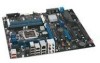
Table 2. Intel Desktop Board DP55KG Components, Desktop Board Features, Label, Description
 |
UPC - 735858205979
View all Intel DP55KG manuals
Add to My Manuals
Save this manual to your list of manuals |
Page 13 highlights
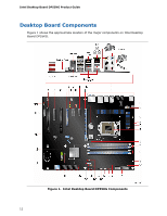
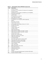
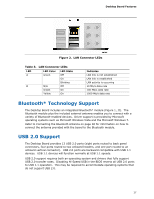
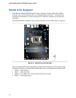
Desktop Board Features Table 2. Intel Desktop Board DP55KG Components Label A B C D E F G H I J K L M N O P Q R S T U V W X Y Z AA BB CC DD EE FF GG HH II JJ KK LL MM Description PCI bus connector PCI Express 2.0 x4 connector (x4 electrical; x16 compatible) PCI bus connector PCI Express 2.0 x8 connector (x8 electrical; x16 compatible) Front panel audio header S/PDIF header PCI Express 2.0 x1 connector Rear chassis fan header PCI Express 2.0 x1 connector PCI Express 2.0 x16 connector (x8/x16 electrical) Battery Back panel connectors Vertical USB connector 12 V processor core voltage connector (2 x 4 pin) Processor fan header Processor LED Voltage regulator LED Processor socket POST code LED display DDR3 Channel A, DIMM 0 and DIMM 1 sockets DDR3 Channel B, DIMM 0 and DIMM 1 sockets Onboard power button Standby power indicator LED Main power connector (2 x 12 pin) SATA drive activity LED Front panel header Back panel CIR transmitter (output) header Front panel CIR receiver (input) header Alternate front panel power LED header Front chassis fan header USB 2.0 headers IEEE 1394a header BIOS configuration jumper block Serial ATA connectors Chassis intrusion header BlueTooth* module Speaker Auxiliary PCI Express graphics power connector (SATA-style) Auxiliary chassis fan header 13
-
 1
1 -
2
-
3
-
4
-
5
-
6
-
7
-
 8
8 -
 9
9 -
 10
10 -
 11
11 -
 12
12 -
 13
13 -
 14
14 -
 15
15 -
 16
16 -
 17
17 -
 18
18 -
19
-
20
-
21
-
22
-
23
-
24
-
25
-
26
-
27
-
28
-
29
-
30
-
31
-
32
-
33
-
34
-
35
-
36
-
37
-
38
-
39
-
40
-
41
-
42
-
43
-
44
-
45
-
46
-
47
-
48
-
49
-
50
-
51
-
52
-
53
-
54
-
55
-
56
-
57
-
58
-
59
-
60
-
61
-
62
-
63
-
64
-
65
-
66
-
67
-
68
-
69
-
70
-
71
-
72
-
73
-
74
-
75
-
76
-
77
-
78
-
79
-
80
-
81
-
82
-
83
-
84
-
85
-
86
-
87
-
88
-
89
-
90
-
91
-
92
 |
 |