Intel DQ45CB Product Guide
Intel DQ45CB - Desktop Board Executive Series Motherboard Manual
 |
UPC - 735858200301
View all Intel DQ45CB manuals
Add to My Manuals
Save this manual to your list of manuals |
Intel DQ45CB manual content summary:
- Intel DQ45CB | Product Guide - Page 1
Intel® Desktop Board DQ45CB Product Guide Order Number: E37720-001 - Intel DQ45CB | Product Guide - Page 2
products are not intended for use in medical, life saving, or life sustaining applications. Intel may make changes to specifications and product descriptions at any time, without notice. Intel Desktop Board DQ45CB may contain design defects or errors known as errata which may cause the product to - Intel DQ45CB | Product Guide - Page 3
board layout, component installation, BIOS update, and regulatory requirements for Intel® Desktop Board DQ45CB. Intended Audience The Product Guide is intended for technically qualified personnel. It is not intended for general audiences. Use Only for Intended Applications All Intel Desktop Boards - Intel DQ45CB | Product Guide - Page 4
Intel Desktop Board DQ45CB Product Guide Conventions The following conventions are used in this manual: CAUTION Cautions warn the user about how to prevent damage to hardware or loss of data. NOTE Notes call attention to important information. Terminology The - Intel DQ45CB | Product Guide - Page 5
Contents 1 Desktop Board Features Desktop Board Components 11 Processor ...13 Main Memory...13 Intel® Q45 Express Chipset 14 Intel Q45 Graphics Subsystem 14 DVI Support 15 PCI Express x16 Graphics 15 Audio Subsystem 16 Legacy Input/Output (I/O) Controller 16 LAN Subsystem 17 LAN Subsystem - Intel DQ45CB | Product Guide - Page 6
Header 48 Chassis Intrusion Header 48 Alternate Front Panel Power LED Header 48 Front Panel Header 49 USB 2.0 Headers 49 IEEE 1394a Header 50 Connecting to the Audio System 50 Connecting Chassis Fan and Power Supply Cables 51 Chassis Fan Cables 51 Power Supply Cables 52 Setting the BIOS - Intel DQ45CB | Product Guide - Page 7
and Component Certifications 85 Figures 1. Intel Desktop Board DQ45CB Components 11 2. LAN Status LEDs 17 3. Intel AMT Status Indicator 19 4. Location of the +5 V Standby Power Indicator 27 5. Installing the I/O Shield 31 6. Intel Desktop Board DQ45CB Mounting Screw Hole Locations 32 7. Lift - Intel DQ45CB | Product Guide - Page 8
2. Intel Desktop Board DQ45CB Components 12 3. Audio Jack Retasking Support 16 4. LAN Connector LEDs 18 5. Intel AMT Status Indicator 19 6. HD Audio Link Header Signal Names 47 7. Front Panel Audio Header Signal Names for HD Audio 47 8. Front Panel Audio Header Signal Names for AC'97 Audio 47 - Intel DQ45CB | Product Guide - Page 9
of the Desktop Board. Table 1. Feature Summary Form Factor Processor Main Memory Chipset Graphics Audio microATX (243.84 millimeters [9.60 inches] x 243.84 millimeters [9.60 inches]) Support for an Intel® processor in the LGA775 package • Four 240-pin, DDR2 1.8 V SDRAM Dual Inline Memory Module - Intel DQ45CB | Product Guide - Page 10
Windows XP Professional • Microsoft Windows XP Professional x64 Edition • Microsoft Windows XP Home For more information about Intel Desktop Board DQ45CB, including the Technical Product Specification (TPS), BIOS updates, and device drivers, go to http://support.intel.com/support/motherboards - Intel DQ45CB | Product Guide - Page 11
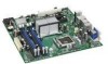
Desktop Board Features Desktop Board Components Figure 1 shows the approximate location of the major components on Intel Desktop Board DQ45CB. Figure 1. Intel Desktop Board DQ45CB Components 11 - Intel DQ45CB | Product Guide - Page 12
intrusion header Alternate front panel power LED header Front panel header BIOS configuration jumper block Serial ATA connectors (5) Speaker High-speed USB 2.0 headers (3) IEEE 1394a header HD audio link header For more information about Intel Desktop Board DQ45CB, go to http://intel.com/design - Intel DQ45CB | Product Guide - Page 13
information about: • Instructions on installing or upgrading the processor, page 33 in Chapter 2 • Supported processors for Intel Desktop Board DQ45CB, http://processormatch.intel.com Main Memory NOTE To be fully compliant with all applicable Intel ® SDRAM memory specifications, the board should be - Intel DQ45CB | Product Guide - Page 14
specifications, http://intel.com/technology/memory/ • Installing memory, page 38 in Chapter 2 • Tested memory, http://cmtlabs.com/mbsearch.asp Intel® Q45 Express Chipset The Intel Q45 Express Chipset consists of the following devices: • Intel 82Q45 Express Chipset Graphics and Memory Controller - Intel DQ45CB | Product Guide - Page 15
connector. When a PCI Express x16, x8, or x4 add-in card is installed on the Desktop Board, the digital portion of the DVI-I port and the DVI-D port are disabled. PCI Express x16 Graphics The GMCH supports an add-in PCI Express discrete graphics card via the PCI Express 2.0 x16 connector as follows - Intel DQ45CB | Product Guide - Page 16
audio (using the back panel audio connectors) and stereo (using the front panel Intel High Definition Audio header) Go to the following locations for more information about: • Audio drivers and utilities http://support.intel.com/support/motherboards/desktop/ • Location of the onboard audio headers - Intel DQ45CB | Product Guide - Page 17
information about LAN software and drivers go to http://support.intel.com/support/motherboards/desktop LAN Subsystem Software For LAN software and drivers, refer to the Intel Desktop Board DQ45CB link on Intel's World Wide Web site at http://support.intel.com/support/motherboards/desktop. LAN Status - Intel DQ45CB | Product Guide - Page 18
Intel Desktop Board DQ45CB Product Guide Table 4 describes the LED states when the board is powered up and the LAN subsystem is operating. Table 4. LAN Connector LEDs LED A (Link) B (Speed) LED Color Green N/A Green Yellow LED State Off On Blinking Off On On Indicates LAN link is not - Intel DQ45CB | Product Guide - Page 19
Desktop Board Features Intel AMT Status Indicator The Intel AMT status indicator (red LED) shows the current state of the Intel Management Engine. Table 5 shows the states of the Intel Management Engine as indicated by the LED. Figure 3 shows the location of the Intel AMT status indicator. Table - Intel DQ45CB | Product Guide - Page 20
Intel Desktop Board DQ45CB Product Guide • Intel Virtualization Technology (Intel® VT) for Directed I/O (Intel® VT-d) Intel VT-d provides additional performance, security and flexibility by providing the VMM with the following capabilities: ⎯ I/O device assignment: for flexibly assigning I/O devices - Intel DQ45CB | Product Guide - Page 21
Desktop Board Features These Intel Trusted Execution Technology capabilities enable more secure platforms to address the increasing frequency and sophistication of software-based attacks. NOTE Intel TXT requires the use of a processor with Intel TXT support. Additionally, thirdparty software may - Intel DQ45CB | Product Guide - Page 22
Intel Desktop Board DQ45CB Product Guide Intel® Rapid Recover Technology (Intel® RRT) The Desktop Board supports Intel Rapid Recover Technology which enables fast and easy recovery of your data in the event of a hard drive failure. It allows you to maintain a complete copy of your primary or master - Intel DQ45CB | Product Guide - Page 23
the computer is booted. If only the supervisor password is set, the computer boots without asking for a password. If both passwords are set, you can enter either password to boot the computer. For instructions on resetting the password, see "Clearing or Changing Passwords" on page 54. Intel® Trusted - Intel DQ45CB | Product Guide - Page 24
DQ45CB Product Guide Hardware Management Features The hardware management features of Intel Desktop Board DQ45CB enable the board to be compatible with the Wired for Management (WfM) specification. The board has several hardware management features including the following: • Fan speed monitoring - Intel DQ45CB | Product Guide - Page 25
can be set by using the Last Power State feature in the BIOS Setup program's Boot menu. The Desktop Board has two power connectors. See Figure 25 on page 52 for the location of the power connectors. Fan Headers The function/operation of the fans is as follows: • The fans are on when the computer is - Intel DQ45CB | Product Guide - Page 26
, the Desktop Board may lose register settings stored in memory. Instantly Available PC technology enables the board to enter the ACPI S3 (Suspend-toRAM) sleep state. While in the S3 sleep state, the computer will appear to be off. If the computer has a dual-colored power LED on the front panel, the - Intel DQ45CB | Product Guide - Page 27
the memory module sockets and the PCI/PCI Express bus connectors. Figure 4. Location of the +5 V Standby Power Indicator For more information on standby current requirements for the Desktop Board, refer to the Technical Product Specification by going to http://support.intel.com/support/motherboards - Intel DQ45CB | Product Guide - Page 28
STAR Category A requirements. For information about the ENERGY STAR specifications, see: http://intel.com/cd/channel/reseller/asmo-na/eng/337748.htm. Speaker A speaker is mounted on the Desktop Board. The speaker provides audible error code (beep code) information during the Power-On Self-Test (POST - Intel DQ45CB | Product Guide - Page 29
Desktop Board • Install and remove a processor • Install and remove memory • Install and remove a PCI Express x16 card • Connect the Serial ATA cables • Connect to the internal headers • Connect to the onboard audio system • Connect chassis fan and power supply cables • Set the BIOS configuration - Intel DQ45CB | Product Guide - Page 30
Intel Desktop Board DQ45CB Product Guide Installation Precautions When you install and test the Intel Desktop Board, observe all warnings and cautions in the installation instructions all warnings and cautions that instruct you to refer computer servicing to qualified technical personnel. Prevent - Intel DQ45CB | Product Guide - Page 31
radio frequency transmissions, protects internal components from dust and foreign objects, and promotes correct airflow within the chassis. Install the I/O shield before installing the Desktop Board in the chassis. Place the shield inside the chassis as shown in Figure 5. Press the shield into place - Intel DQ45CB | Product Guide - Page 32
can result in personal injury or equipment damage. Refer to your chassis manual for instructions on installing and removing the Desktop Board. Figure 6 shows the location of the mounting screw holes for Intel Desktop Board DQ45CB. Figure 6. Intel Desktop Board DQ45CB Mounting Screw Hole Locations 32 - Intel DQ45CB | Product Guide - Page 33
section contains information on how to install and remove a processor on the Desktop Board. Installing a Processor CAUTION Before installing or removing the processor, make sure the AC power has been removed by unplugging the power cord from the computer; the standby power LED should not be lit (see - Intel DQ45CB | Product Guide - Page 34
Intel Desktop Board DQ45CB Product Guide 3. Lift the load plate (Figure 8, A). Do not touch the socket contacts (Figure 8, B). Figure 8. Lift the Load Plate 4. Remove the plastic protective socket cover from the - Intel DQ45CB | Product Guide - Page 35
Installing and Replacing Desktop Board Components 5. Remove the processor from the protective processor cover. Hold the processor only at the edges, being with the socket (Figure 11, C). Lower the processor straight down without tilting or sliding it in the socket. Figure 11. Install the Processor 35 - Intel DQ45CB | Product Guide - Page 36
socket lever (Figure 12, B). Figure 12. Close the Load Plate Installing a Processor Fan Heat Sink Intel Desktop Board DQ45CB has mounting holes for a processor fan heat sink. For instructions on how to attach the processor fan heat sink to the Desktop Board, refer to the boxed processor manual. 36 - Intel DQ45CB | Product Guide - Page 37
Installing and Replacing Desktop Board Components Connecting the Processor Fan Heat Sink Cable Connect the processor fan heat sink cable to the 4-pin processor fan header (see Figure 13). Removing the Processor For instructions on how to remove the processor fan heat sink and processor, refer to - Intel DQ45CB | Product Guide - Page 38
Intel Desktop Board DQ45CB Product Guide Installing and Removing Memory Intel Desktop Board DQ45CB has four 240-pin DDR2 DIMM sockets arranged as DIMM 0 and DIMM 1 in both Channel A and Channel B. NOTE Regardless of the memory configuration used (dual or single channel), Channel A, DIMM 0 must - Intel DQ45CB | Product Guide - Page 39
Installing and Replacing Desktop Board Components If additional memory is to be used, install another matched pair of DIMMs in DIMM 1 (black) in channels A and B (see Figure 15). Figure 15. Dual Channel Memory Configuration with Four DIMMs Three DIMMs If you want to use three DIMMs in a dual-channel - Intel DQ45CB | Product Guide - Page 40
Intel Desktop Board DQ45CB Product Guide Installing DIMMs To make sure you have the correct DIMM, place it on the illustration of the DDR2 DIMM in Figure 17. All the notches should match with the DDR2 DIMM. Figure 17. Use DDR2 DIMMs 40 - Intel DQ45CB | Product Guide - Page 41
and Replacing Desktop Board Components To install a DIMM, follow these steps: 1. Observe the precautions in "Before You Begin" on page 29. 2. Turn off all peripheral devices connected to the computer. Turn off the computer and disconnect the AC power cord. 3. Remove the computer's cover and - Intel DQ45CB | Product Guide - Page 42
Intel Desktop Board DQ45CB Product Guide 7. Insert the bottom edge of the DIMM into the socket. 8. When the DIMM is inserted, push down on the top edge of the DIMM until the retaining clips snap into place. Make sure the clips are firmly in place. 9. Replace the computer's cover and reconnect the AC - Intel DQ45CB | Product Guide - Page 43
Depending on the over-current protection of the power supply, certain Desktop Board components and/or traces may be damaged. Installing a PCI Express x16 Card 1. Observe the precautions in " bracket to the chassis back panel with a screw (Figure 19, B). Figure 19. Installing a PCI Express x16 Card 43 - Intel DQ45CB | Product Guide - Page 44
Intel Desktop Board DQ45CB Product Guide Removing the PCI Express x16 Card Follow these instructions to remove the PCI Express x16 card from the connector: 1. Observe the precautions in "Before You Begin" on page 29. 2. Remove the screw (Figure 20, A) - Intel DQ45CB | Product Guide - Page 45
Installing and Replacing Desktop Board Components Connecting Serial ATA (SATA) Cables SATA cables support the Serial ATA protocol. Each cable can be used to connect a single SATA drive to the Desktop Board. For correct cable function: 1. Observe the precautions in "Before You Begin" on page 29. 2. - Intel DQ45CB | Product Guide - Page 46
Intel Desktop Board DQ45CB Product Guide Connecting to Internal Headers Before connecting cables to the internal headers, observe the precautions in "Before You Begin" on page 29. Figure 22 shows the location of the internal headers and connectors. Item Description A HD Audio Link B HD Audio C - Intel DQ45CB | Product Guide - Page 47
Installing and Replacing Desktop Board Components HD Audio Link Header See Figure 22, A for the location of the HD Audio Link header. Table 6 shows the pin assignments for the header. Table 6. HD Audio Link Header Signal Names Pin Signal Name 1 BCLK 3 RST# Pin Signal Name 2 Ground 4 - Intel DQ45CB | Product Guide - Page 48
Intel Desktop Board DQ45CB Product Guide Serial Port Header See Figure 22, D for the location of the serial port header. Table 9 shows the pin assignments for the header. Table 9. Serial Port Header Signal Names Pin Signal Name 1 DCD 3 TXD# 5 Ground 7 RTS 9 RI Pin Signal Name 2 RXD - Intel DQ45CB | Product Guide - Page 49
Installing and Replacing Desktop Board Components Front Panel Header See Figure 22, F for the location of the multi-colored front panel header. Table 12 shows the pin assignments for the front panel header. Table 12. Front Panel Header Signal Names Pin Description In/Out Pin Description Hard - Intel DQ45CB | Product Guide - Page 50
Intel Desktop Board DQ45CB Product Guide IEEE 1394a Header See Figure 22, H for the location of the IEEE 1394a header. Table 14 shows the pin assignments for the header. Table 14. IEEE 1394a Header Signal Names Pin Signal Name 1 TPA1+ 3 Ground 5 TPA2+ 7 +12 V 9 Key (no pin) Pin - Intel DQ45CB | Product Guide - Page 51
Installing and Replacing Desktop Board Components Connecting Chassis Fan and Power Supply Cables Chassis Fan Cables Connect chassis fan cables to the chassis fan headers on the Desktop Board. Figure 24 shows the location of the chassis fan headers. Figure 24. Location of the Chassis Fan Headers 51 - Intel DQ45CB | Product Guide - Page 52
Intel Desktop Board DQ45CB Product Guide Power Supply Cables CAUTION Failure to use an appropriate power supply and/or not connecting the 12 V (2 x 2 pin) power connector to the Desktop Board may result in damage to the board or the system may not function properly. The 2 x 12 pin main power - Intel DQ45CB | Product Guide - Page 53
Installing and Replacing Desktop Board Components Setting the BIOS Configuration Jumper NOTE Always turn off the power and unplug the power cord from the computer before moving the jumper. Moving the jumper with the power on may result in unreliable computer operation. Figure 26 shows the location - Intel DQ45CB | Product Guide - Page 54
Intel Desktop Board DQ45CB Product Guide Table 15. Jumper Settings for the BIOS Setup Program Modes Jumper Setting Mode Normal (default) (1-2) Description The BIOS uses the current configuration and passwords for booting. Configure (2-3) After the Power-On Self-Test (POST) runs, the BIOS - Intel DQ45CB | Product Guide - Page 55
Installing and Replacing Desktop Board Components 9. Press to save the current values and exit Setup. 10. Turn off the computer. Disconnect the computer's power cord from the AC power source. 11. Remove the computer cover. 12. To restore normal operation, place the jumper on pins 1-2 as shown - Intel DQ45CB | Product Guide - Page 56
Intel Desktop Board DQ45CB Product Guide FORHOLDSREGEL Eksplosionsfare, hvis batteriet erstattes med et batteri af en forkert type. Batterier bør om muligt genbruges. Bortskaffelse af brugte batterier bør foregå i overensstemmelse med gældende miljø - Intel DQ45CB | Product Guide - Page 57
Installing and Replacing Desktop Board Components ATENÇÃO Haverá risco de explosão se a bateria for substituída por um tipo de bateria incorreto. As baterias devem ser recicladas nos locais apropriados. A eliminação de baterias usadas deve ser feita de acordo com as regulamentações ambientais da - Intel DQ45CB | Product Guide - Page 58
Intel Desktop Board DQ45CB Product Guide PRECAUŢIE Risc de explozie, dacă bateria este înlocuită cu un tip de baterie necorespunzător. Bateriile trebuie reciclate, dacă este posibil. Depozitarea bateriilor uzate - Intel DQ45CB | Product Guide - Page 59
Installing and Replacing Desktop Board Components 59 - Intel DQ45CB | Product Guide - Page 60
Intel Desktop Board DQ45CB Product Guide To replace the battery, follow these steps: 1. Observe the precautions in "Before You Begin" (see page 29). 2. Turn off all peripheral devices connected to the computer. Disconnect the computer's power cord from the AC power source (wall outlet or power - Intel DQ45CB | Product Guide - Page 61
use of Windows-based installation wizards. To update the BIOS with the Intel Express BIOS Update utility: 1. Go to the Intel World Wide Web site: http://support.intel.com/support/motherboards/desktop/ 2. Navigate to the Intel Desktop Board DQ45CB page. Under the "Software and drivers" heading, click - Intel DQ45CB | Product Guide - Page 62
the Intel Desktop Board DQ45CB page on the Intel World Wide Web site at http://support.intel.com/support/motherboards/desktop. Navigate to the Intel Desktop Board DQ45CB page. Under the "Software and drivers" heading, click on "Latest BIOS" to locate the latest BIOS files. Click on the "BIOS Update - Intel DQ45CB | Product Guide - Page 63
USB flash drive or other bootable USB media. The Iflash Memory update utility allows you to: • Update the BIOS and Intel Management Engine in flash memory • Update the language section of the BIOS NOTE Review the instructions distributed with the update utility before attempting a BIOS update. 63 - Intel DQ45CB | Product Guide - Page 64
. Due to BIOS size and recovery requirements, a CD-R with the .BIO file in the root directory will be required. NOTE For more information about updating the Intel Desktop Board BIOS or recovering from a BIOS update failure, go to http://support.intel.com/support/motherboards/desktop/sb/CS-022312 - Intel DQ45CB | Product Guide - Page 65
4 Configuring for RAID (Intel® Matrix Storage Technology (Intel® MST)) NOTE Intel Matrix Storage Technology requires Microsoft Windows Vista or Microsoft Windows XP operating system and SATA hard drives. Configuring the BIOS for Intel Matrix Storage Technology 1. Assemble your system and attach one - Intel DQ45CB | Product Guide - Page 66
Intel Desktop Board DQ45CB Product Guide Loading the Intel Matrix Storage Technology RAID Drivers and Software 1. Begin Windows Setup by booting from the Windows installation CD. 2. If you will be using Microsoft Windows XP, press at the beginning of Windows Setup to install a third-party SCSI - Intel DQ45CB | Product Guide - Page 67
previously not set to RAID and you already have an operating system installed, you must reinstall it. Follow the instructions in Chapter 4 to install the Intel Matrix Storage RAID driver during the operating system installation. 5. Exit and save settings. Proceed to "Creating a Recovery Volume." 67 - Intel DQ45CB | Product Guide - Page 68
Intel Desktop Board DQ45CB Product Guide Creating a Recovery Volume A recovery volume consists of two disks - a master disk and a recovery disk. A recovery volume can be created with either the RAID Option ROM (OROM) or the Intel® Matrix Storage Console application. Creating a Recovery Volume Using - Intel DQ45CB | Product Guide - Page 69
1. Make sure that the recovery volume is in Update On Request mode. 2. Then right-click on the recovery volume name and select Access Recovery Drive Files. 3. Select OK on the information dialog box. The recovery disk will now be mounted and can be seen in Microsoft Windows Explorer. NOTE Individual - Intel DQ45CB | Product Guide - Page 70
Intel Desktop Board DQ45CB Product Guide To un-mount the recovery disk, complete the following steps: 1. In the Advanced mode, right-click on the recovery volume name. 2. Select Access Recovery Drive Files. 3. Select OK on the information dialog box. The recovery disk is now un-mounted and reappears - Intel DQ45CB | Product Guide - Page 71
Messages and Indicators Intel Desktop Board DQ45CB reports POST errors in two ways: • By sounding a beep code • By displaying an error message on the monitor BIOS Beep Codes The BIOS also issues a beep code (one long tone followed by two short tones) during POST if the video configuration fails - Intel DQ45CB | Product Guide - Page 72
Intel Desktop Board DQ45CB Product Guide 72 - Intel DQ45CB | Product Guide - Page 73
Ecology statements • Electromagnetic Compatibility (EMC) regulations • Product certifications Safety Standards Intel Desktop Board DQ45CB complies with the safety standards stated in Table 18 when correctly installed in a compatible host system. Table 18. Safety Standards Regulation CSA/UL - Intel DQ45CB | Product Guide - Page 74
Intel Desktop Board DQ45CB Product Guide European Union Declaration of Conformity Statement We, Intel Corporation, declare under our sole responsibility that the product Intel® Desktop Board DQ45CB is in conformity with all applicable essential requirements necessary for CE marking, following the - Intel DQ45CB | Product Guide - Page 75
. Please consult http://intel.com/intel/other/ehs/product_ecology for the details of this program, including the scope of covered products, available locations, shipping instructions, terms and conditions, etc Intel Product Recycling Program http://intel.com/intel/other/ehs/product_ecology 75 - Intel DQ45CB | Product Guide - Page 76
Intel Desktop Board DQ45CB Product Guide Deutsch Als Teil von Intels Engagement für den Umweltschutz hat das Unternehmen das Intel Produkt-Recyclingprogramm implementiert, das Einzelhandelskunden von Intel Markenprodukten ermöglicht, gebrauchte Produkte an ausgewählte Standorte für ordnungsgemäßes - Intel DQ45CB | Product Guide - Page 77
de Reciclagem de Produtos para que os consumidores finais possam enviar produtos Intel usados para locais selecionados, onde esses produtos são reciclados de maneira adequada. Consulte o site http://intel.com/intel/other/ehs/product_ecology (em Inglês) para obter os detalhes sobre este programa - Intel DQ45CB | Product Guide - Page 78
Intel Desktop Board DQ45CB Product Guide Lead-free 2LI/Pb-free 2LI Board The electronics industry is acceptable because of the RoHS "flip chip" or "die bump" interconnect exemption. Intel Desktop Board DQ45CB is a lead-free second level interconnect product. Table 19 shows the lead-free - Intel DQ45CB | Product Guide - Page 79
components in which the Pb concentration level in the Desktop Board substrate and the solder connections from the board to or the components (second-level interconnect) is 0.01% or 100 ppm) by weight of homogeneous material. Intel Desktop Board DQ45CB complies with these restrictions. 79 - Intel DQ45CB | Product Guide - Page 80
Intel Desktop Board DQ45CB Product Guide China RoHS "China RoHS" is the term used by However, the China RoHS regulation requires specific product marking and a selfdeclaration of the controlled substances contained in each product. Intel Desktop Board DQ45CB is a China RoHS-compliant product. - Intel DQ45CB | Product Guide - Page 81
Regulatory Compliance The China MII stipulates that a material Self Declaration Table (SDT) must be included in a product's user documentation. The SDT for Intel Desktop Board DQ45CB is shown in Figure 28. Figure 28. Intel Desktop Board DQ45CB China RoHS Material Self Declaration Table 81 - Intel DQ45CB | Product Guide - Page 82
Intel Desktop Board DQ45CB Product Guide EMC Regulations Intel Desktop Board DQ45CB complies with the EMC regulations stated in Table 21 when correctly installed in a compatible host system. Table 21. EMC Regulations Regulation (Class B) FCC 47 CFR Part 15, Subpart B ICES-003 Issue 4 EN55022: - Intel DQ45CB | Product Guide - Page 83
environments. Ensure Electromagnetic Compatibility (EMC) Compliance Before computer integration, make sure that the power supply and other marked accordingly. Pay close attention to the following when reading the installation instructions for the host chassis, power supply, and other modules: - Intel DQ45CB | Product Guide - Page 84
Board DQ45CB Product Guide Product Certifications Board-Level Certification Markings Intel Desktop Board DQ45CB has the product certification markings shown in Table 22. Table 22. Product Certification Markings Description UL joint US/Canada Recognized Component mark. Includes adjacent UL file - Intel DQ45CB | Product Guide - Page 85
interference (EMI) requirements. In Canada A nationally recognized certification mark such as CSA or cUL signifies compliance with safety requirements. The Industry Canada statement at the front of this product guide demonstrates compliance with Canadian EMC regulations. 85 - Intel DQ45CB | Product Guide - Page 86
Intel Desktop Board DQ45CB Product Guide 86
-
 1
1 -
 2
2 -
 3
3 -
 4
4 -
 5
5 -
 6
6 -
 7
7 -
8
-
9
-
10
-
11
-
12
-
13
-
14
-
15
-
16
-
17
-
18
-
19
-
20
-
21
-
22
-
23
-
24
-
25
-
26
-
27
-
28
-
29
-
30
-
31
-
32
-
33
-
34
-
35
-
36
-
37
-
38
-
39
-
40
-
41
-
42
-
43
-
44
-
45
-
46
-
47
-
48
-
49
-
50
-
51
-
52
-
53
-
54
-
55
-
56
-
57
-
58
-
59
-
60
-
61
-
62
-
63
-
64
-
65
-
66
-
67
-
68
-
69
-
70
-
71
-
72
-
73
-
74
-
75
-
76
-
77
-
78
-
79
-
80
-
81
-
82
-
83
-
84
-
85
-
86
 |
 |

Intel
®
Desktop Board DQ45CB
Product Guide
Order Number:
E37720-001