Intel DQ45CB Product Guide - Page 37
Connecting the Processor Fan Heat Sink Cable, Removing the Processor,
 |
UPC - 735858200301
View all Intel DQ45CB manuals
Add to My Manuals
Save this manual to your list of manuals |
Page 37 highlights
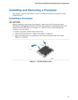
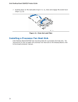
Installing and Replacing Desktop Board Components Connecting the Processor Fan Heat Sink Cable Connect the processor fan heat sink cable to the 4-pin processor fan header (see Figure 13). A fan with a 4-pin connector as shown in Figure 13, A is recommended; however, a fan with a 3-pin connector (Figure 13, B) can be used. However, since a fan with a 3-pin connector cannot use the onboard fan control, the fan will always operate at full speed. Figure 13. Connecting the Processor Fan Heat Sink Cable Removing the Processor For instructions on how to remove the processor fan heat sink and processor, refer to the processor installation manual. 37
-
 1
1 -
2
-
3
-
4
-
5
-
6
-
7
-
8
-
9
-
10
-
11
-
12
-
13
-
14
-
15
-
16
-
17
-
18
-
19
-
20
-
21
-
22
-
23
-
24
-
25
-
26
-
27
-
28
-
29
-
30
-
31
-
 32
32 -
 33
33 -
 34
34 -
 35
35 -
 36
36 -
 37
37 -
 38
38 -
 39
39 -
 40
40 -
 41
41 -
 42
42 -
43
-
44
-
45
-
46
-
47
-
48
-
49
-
50
-
51
-
52
-
53
-
54
-
55
-
56
-
57
-
58
-
59
-
60
-
61
-
62
-
63
-
64
-
65
-
66
-
67
-
68
-
69
-
70
-
71
-
72
-
73
-
74
-
75
-
76
-
77
-
78
-
79
-
80
-
81
-
82
-
83
-
84
-
85
-
86
 |
 |
Installing and Replacing Desktop Board Components
37
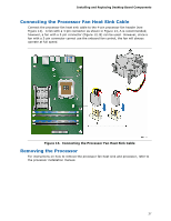
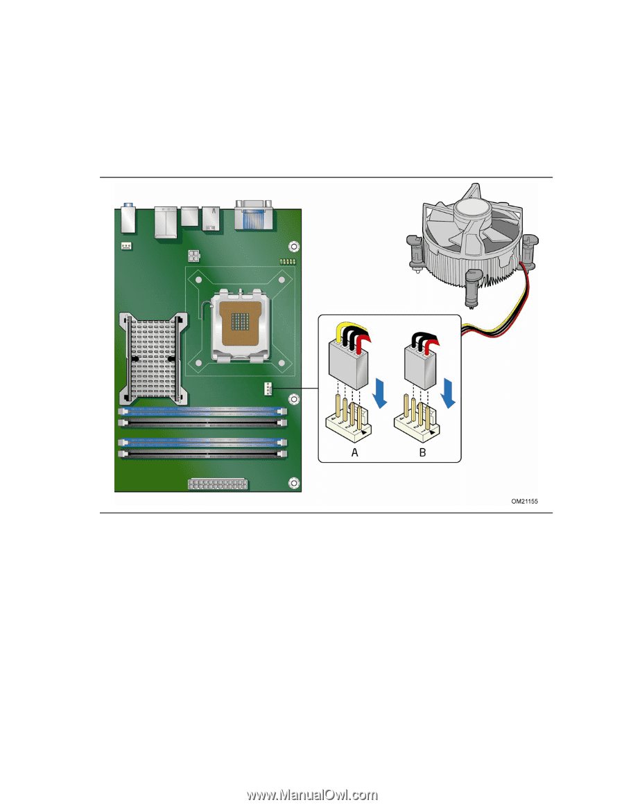
Connecting the Processor Fan Heat Sink Cable
Connect the processor fan heat sink cable to the 4-pin processor fan header (see
Figure 13).
A fan with a 4-pin connector as shown in Figure 13, A is recommended;
however, a fan with a 3-pin connector (Figure 13, B) can be used.
However, since a
fan with a 3-pin connector cannot use the onboard fan control, the fan will always
operate at full speed.
Figure 13.
Connecting the Processor Fan Heat Sink Cable
Removing the Processor
For instructions on how to remove the processor fan heat sink and processor, refer to
the processor installation manual.