Intel DQ45CB Product Guide - Page 50
IEEE 1394a Header, Connecting to the Audio System - audio drivers
 |
UPC - 735858200301
View all Intel DQ45CB manuals
Add to My Manuals
Save this manual to your list of manuals |
Page 50 highlights
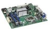
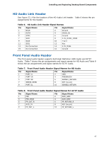
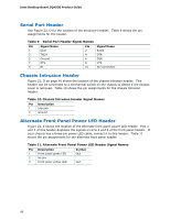
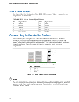
Intel Desktop Board DQ45CB Product Guide IEEE 1394a Header See Figure 22, H for the location of the IEEE 1394a header. Table 14 shows the pin assignments for the header. Table 14. IEEE 1394a Header Signal Names Pin Signal Name 1 TPA1+ 3 Ground 5 TPA2+ 7 +12 V 9 Key (no pin) Pin Signal Name 2 TPA1- 4 Ground 6 TPA2- 8 +12 V 10 Ground Connecting to the Audio System After installing the Analog Devices audio driver from the Intel Express Installer DVD-ROM, the multi-channel audio feature can be enabled. Figure 23 shows the default back panel audio connector assignments. The audio connectors are retaskable via audio software. Table 3 on page 16 lists the supported audio connector assignments. Item Description A Line In B Line Out C Mic In Figure 23. Back Panel Audio Connectors NOTE The back panel line out connector is designed to power either headphones or amplified speakers only. Poor audio quality may occur if passive (non-amplified) speakers are connected to this output. 50
-
 1
1 -
2
-
3
-
4
-
5
-
6
-
7
-
8
-
9
-
10
-
11
-
12
-
13
-
14
-
15
-
16
-
17
-
18
-
19
-
20
-
21
-
22
-
23
-
24
-
25
-
26
-
27
-
28
-
29
-
30
-
31
-
32
-
33
-
34
-
35
-
36
-
37
-
38
-
39
-
40
-
41
-
42
-
43
-
44
-
 45
45 -
 46
46 -
 47
47 -
 48
48 -
 49
49 -
 50
50 -
 51
51 -
 52
52 -
 53
53 -
 54
54 -
 55
55 -
56
-
57
-
58
-
59
-
60
-
61
-
62
-
63
-
64
-
65
-
66
-
67
-
68
-
69
-
70
-
71
-
72
-
73
-
74
-
75
-
76
-
77
-
78
-
79
-
80
-
81
-
82
-
83
-
84
-
85
-
86
 |
 |