Intel RS25NB008 User Guide - Page 21
Intel® RAID Controller RS25NB008 Characteristics
 |
View all Intel RS25NB008 manuals
Add to My Manuals
Save this manual to your list of manuals |
Page 21 highlights
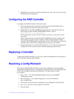
3 Intel® RAID Controller RS25NB008 Characteristics J1A2 J1A1 J2A1 J2A3J2A2 J4A1 J4A2 J5A2 J6A1 J1A3 J1B1 J2B1 J5B1 Figure 3. Card Layout AF004152 The Cache Memory Board component is a printed circuit board with RAID controller cache memory chips on it that mounts directly to the base controller through the Memory Board Connector J2 and is secured by one screw. It provides a 20-pin connector for remote battery backup module installation support. Figure 4. Cache Memory Board Intel® RAID Controller RS25NB008 Hardware User's Guide 11
-
 1
1 -
2
-
3
-
4
-
5
-
6
-
7
-
8
-
9
-
10
-
11
-
12
-
13
-
14
-
15
-
 16
16 -
 17
17 -
 18
18 -
 19
19 -
 20
20 -
 21
21 -
 22
22 -
 23
23 -
 24
24 -
 25
25 -
 26
26 -
27
-
28
-
29
-
30
-
31
-
32
-
33
-
34
-
35
-
36
-
37
-
38
-
39
-
40
-
41
-
42
-
43
-
44
-
45
-
46
-
47
-
48
-
49
-
50
 |
 |
Intel® RAID Controller RS25NB008 Hardware User’s Guide
11
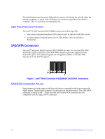
3
Intel
®
RAID Controller RS25NB008
Characteristics
Figure 3. Card Layout
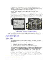
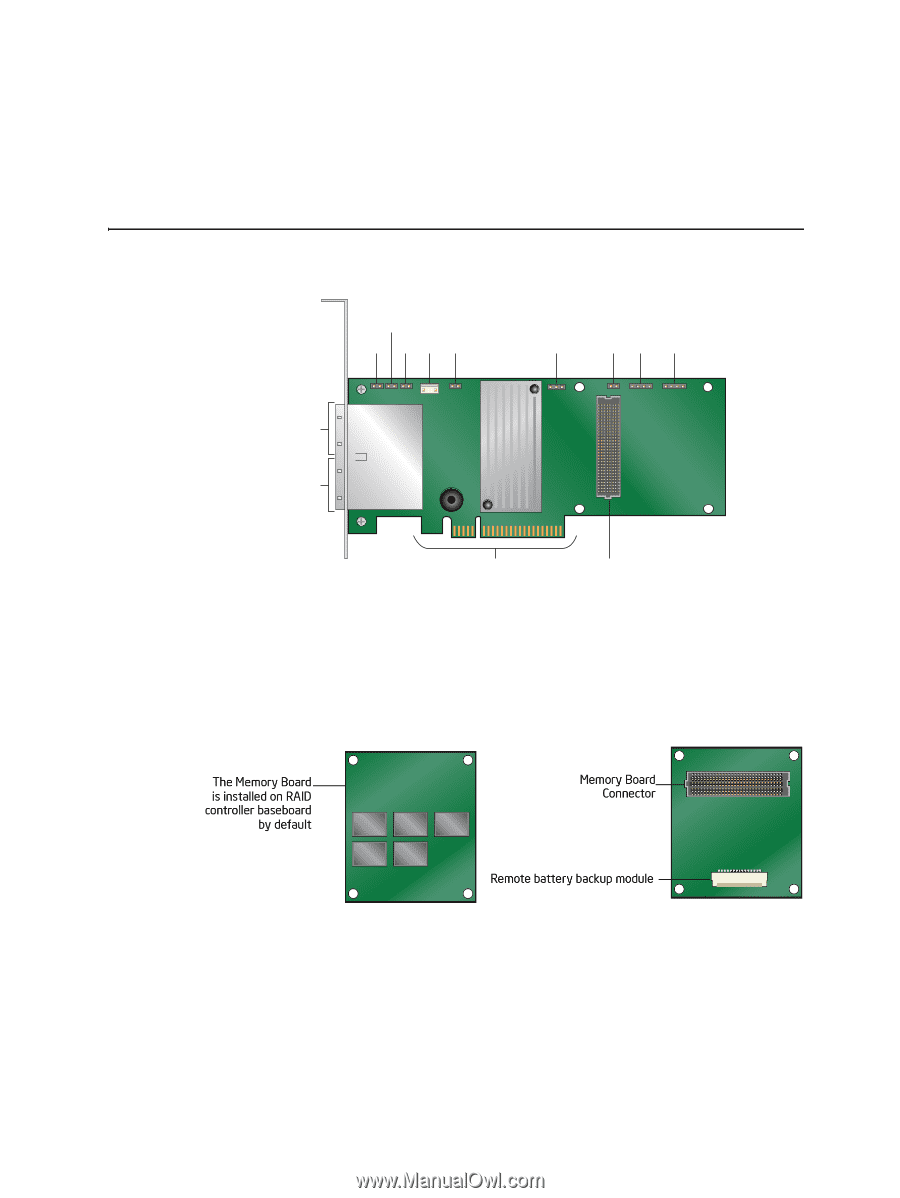
The Cache Memory Board component is a printed circuit board with RAID controller
cache memory chips on it that mounts directly to the base controller through the Memory
Board Connector J2 and is secured by one screw. It provides a 20-pin connector for
remote battery backup module installation support.
Figure 4. Cache Memory Board
AF004152
J5B1
J2B1
J1A1
J1A2
J2A1
J2A3
J2A2
J4A1
J4A2
J5A2
J6A1
J1B1
J1A3