Intel RS25NB008 User Guide - Page 22
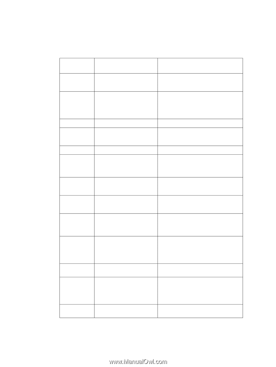
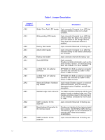
Table 1. Jumper Description, Jumper, Connector, Description
 |
View all Intel RS25NB008 manuals
Add to My Manuals
Save this manual to your list of manuals |
Page 22 highlights
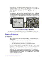
Table 1. Jumper Description s Jumper / Connector J1A2 J1A1 J4A2 J2A1 J2A2 J4A1 J1A3 J1B1 J2A3 J2B1 J5A2 J5B1 J6A1 Type Description Global Drive Fault LED header 2-pin connector Connects to an LED that indicates whether a drive is in a fault condition. Write-pending LED header 2-pin connector Connects to an LED that indicates when the data in the cache has yet to be written to the storage devices. Used when the write-back feature is enabled. Factory Test header 2-pin connector Reserved for factory use. Activity LED header 2-pin connector Connects to an LED that indicates activity on the drives connected to the controller. Factory test header 2-pin connector reserved for factory use. Serial EEPROM 2-pin connector Provides controller information, such as the serial number, revision, and manufacturing date. The default is no shunt installed. x4 SAS Ports 0-3 external connector SFF-8088 mini SAS 4e external connector Connects the controller by cable to SAS drives or SATA 2 drives. x4 SAS Ports 4-7 external connector SFF-8088 mini SAS 4e external connector Connects the controller by cable to SAS drives or SATA 2 drives. Advanced Software Hardware Key Header 3-pin header Enables support for selected advanced features, such as recovery, Supersized cache, FastPath, and full disk encryption. Standard edge card connector The RAID controller interfaces with the host system though a standard edge card. This interface provides power to the board and an I2C interface connected to the I2C bus for IPMI. UART connector for the expander 4-pin connector Reserved for factory use. Board-to-board Connector for the memory board Provides an interface to the memory board that contains 1GB 667MHz DDR3 memory. The memory board can be connected to an optional Intel® RAID Smart Battery AXXRSBBU9. UART connector for the expander 4-pin connector Reserved for factory use. 12 Intel® RAID Controller RS25NB008 Hardware User's Guide
-
 1
1 -
2
-
3
-
4
-
5
-
6
-
7
-
8
-
9
-
10
-
11
-
12
-
13
-
14
-
15
-
16
-
 17
17 -
 18
18 -
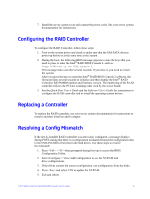 19
19 -
 20
20 -
 21
21 -
 22
22 -
 23
23 -
 24
24 -
 25
25 -
 26
26 -
 27
27 -
28
-
29
-
30
-
31
-
32
-
33
-
34
-
35
-
36
-
37
-
38
-
39
-
40
-
41
-
42
-
43
-
44
-
45
-
46
-
47
-
48
-
49
-
50
 |
 |