Intel RT3WB080 Hardware User Guide - Page 24
Technical Specifications - battery
 |
View all Intel RT3WB080 manuals
Add to My Manuals
Save this manual to your list of manuals |
Page 24 highlights
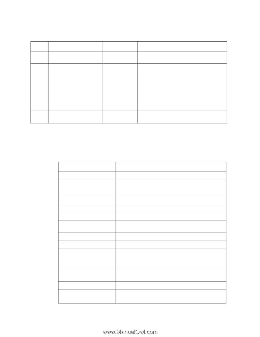
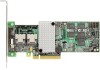
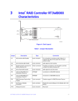
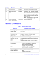
Jumper Description JT11 Keyed I2C Connector JT12 Individual Drive Fault LED header Type 3-pin keyed connector 8 x 2 header JT13 Universal Asynchronous 4-pin connector Receiver/Transmitter (UART) Comments Out-of-band enclosure management (SES2) Indicates drive faults. There is one LED per port. When lit, each LED indicates the corresponding drive has failed or is in the Unconfigured-Bad state. The LEDs function in a direct-attach configuration (there are no SAS expanders). Direct attach is defined as a maximum of one drive connected directly to each port. Note: This header is used for RAID controllers with internal SAS ports only. For factory and debug use Technical Specifications Table 2. Technical Specifications Specification RAID-on-Chip (ROC) Operating voltage Card size Array interface to host SATA bus speed SATA ports Physical and virtual drive support Cache Firmware Compatible devices Cabling Redundant configuration Enclosure management Intel® RAID Controller RT3WB080 LSISAS2108 Integrated ROC, 800 MHz +3.3 V, +12 V Low profile, extended half-length (6.6-inch, MD2) PCI Express* Revision 2.0, x8 lane width 5.0 Gb/s Up to 6 Gb/s per port, point-to-point 2x4 internal ports, 16 devices per port with expanders 16 physical drives, 64 virtual drives, and 32 RAID arrays per controller 256 MB DDR2 800 MHz SDRAM, optional battery backup 8 MB in reflashable flash ROM • 2.5-inch and 3.5-inch SATA III or SATA II drives • Non disk devices including expanders • Can support drives of mixed capacity • Small, thin cables that do not restrict airflow • Shared connectors for multiple drives 32 KB NVRAM and config-on-disk (COD) • SGPIO • In-band and out-of-band SES 14 Intel® RAID Controller RT3WB080 Hardware User's Guide
-
 1
1 -
2
-
3
-
4
-
5
-
6
-
7
-
8
-
9
-
10
-
11
-
12
-
13
-
14
-
15
-
16
-
17
-
18
-
 19
19 -
 20
20 -
 21
21 -
 22
22 -
 23
23 -
 24
24 -
 25
25 -
 26
26 -
 27
27 -
 28
28 -
 29
29 -
30
-
31
-
32
-
33
-
34
-
35
-
36
-
37
-
38
-
39
-
40
-
41
-
42
-
43
-
44
 |
 |