Intel S5000PSL User Guide - Page 7
Preface, About this Manual, Manual Organization - support
 |
UPC - 735858196055
View all Intel S5000PSL manuals
Add to My Manuals
Save this manual to your list of manuals |
Page 7 highlights
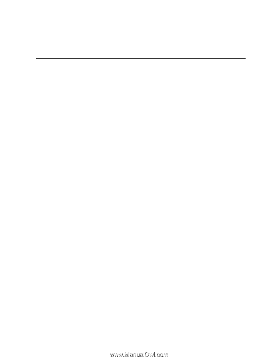
Preface About this Manual Thank you for purchasing and using the Intel® Server Board S5000PSL. Multiple versions of the Intel® Server Board S5000PSL are available. This manual applies to server boards with the following product codes: • S5000PSLSATA / S5000PSLSATAR • S5000XSLSATA / S5000PXSLSATAR • S5000PSLSAS / S5000PSLSASR • S5000PSLROMB / S5000PSLROMBR Where a feature varies from one product to the next, the difference will be noted in this document. Unless specified, features apply to all versions of the server board. Note: Unless otherwise indicated, any references to the product code S5000PSLSATA or S5000PSLSATAR also apply to product codes S5000XSLSATA or S5000XSLSATAR. This manual is written for system technicians who are responsible for troubleshooting, upgrading, and repairing this server board. This document provides a brief overview of the features of the board/chassis, a list of accessories or other components you may need, troubleshooting information, and instructions on how to add and replace components on the Intel® Server Board S5000PSL. For the latest version of this manual, see http://support.intel.com/support/motherboards/server/S5000PSL/. Manual Organization Chapter 1 provides a brief overview of the Server Board S5000PSL. In this chapter, you will find a list of the server board features, a photo of the product, and product diagrams to help you identify components and their locations. Chapter 2 provides instructions on using the utilities that are shipped with the board or that may be required to update the system. This includes how to navigate through the BIOS Setup screens, how to perform a BIOS update, and how to reset the password or CMOS. Information about the specific BIOS settings and screens is available in the Technical Product Specification. See "Additional Information and Software" on page viii for a link to the Technical Product Specification. Chapter 3 provides instructions on adding and replacing components. Use this chapter for step-by-step instructions and diagrams for installing or replacing components such as the memory, processor, and the CMOS battery.
-
 1
1 -
 2
2 -
 3
3 -
 4
4 -
 5
5 -
 6
6 -
 7
7 -
 8
8 -
 9
9 -
 10
10 -
 11
11 -
 12
12 -
13
-
14
-
15
-
16
-
17
-
18
-
19
-
20
-
21
-
22
-
23
-
24
-
25
-
26
-
27
-
28
-
29
-
30
-
31
-
32
-
33
-
34
-
35
-
36
-
37
-
38
-
39
-
40
-
41
-
42
-
43
-
44
-
45
-
46
-
47
-
48
-
49
-
50
-
51
-
52
-
53
-
54
-
55
-
56
-
57
-
58
-
59
-
60
-
61
-
62
-
63
-
64
-
65
-
66
-
67
-
68
-
69
-
70
-
71
-
72
-
73
-
74
-
75
-
76
-
77
-
78
-
79
-
80
-
81
-
82
-
83
-
84
-
85
-
86
-
87
-
88
-
89
-
90
 |
 |