Intel SE7501WV2 Product Guide - Page 25
Install the Server Board, A.
 |
UPC - 735858159388
View all Intel SE7501WV2 manuals
Add to My Manuals
Save this manual to your list of manuals |
Page 25 highlights
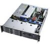
Install the Server Board CAUTION Do not install any server board support bumpers in the SR2300 chassis. System components must be installed in the order presented below. If installed in a different order, component damage may occur. 1. Ensure that the insulator sheet is seated securely over the standoffs, is laying flat on the chassis floor, and that the edge of the sheet is seated below the studs in the rear chassis wall. (Figure 10, A.) 2. Remove the server board from its packaging and antistatic bag. 3. While placing the board on the chassis standoffs, carefully position the board I/O connectors (Figure 10, B) in the rear chassis I/O openings. 4. Adjust board position so that the mounting holes rest securely on the corresponding shouldered standoffs (Figure 10, C). 5. Attach the board to the chassis using the three screws shipped in the chassis accessory kit (Figure 10, D). Assembling the System 25
-
 1
1 -
2
-
3
-
4
-
5
-
6
-
7
-
8
-
9
-
10
-
11
-
12
-
13
-
14
-
15
-
16
-
17
-
18
-
19
-
 20
20 -
 21
21 -
 22
22 -
 23
23 -
 24
24 -
 25
25 -
 26
26 -
 27
27 -
 28
28 -
 29
29 -
 30
30 -
31
-
32
-
33
-
34
-
35
-
36
-
37
-
38
-
39
-
40
-
41
-
42
-
43
-
44
-
45
-
46
-
47
-
48
-
49
-
50
-
51
-
52
-
53
-
54
-
55
-
56
-
57
-
58
-
59
-
60
-
61
-
62
-
63
-
64
-
65
-
66
-
67
-
68
-
69
-
70
-
71
-
72
-
73
-
74
-
75
-
76
-
77
-
78
-
79
-
80
-
81
-
82
-
83
-
84
-
85
-
86
-
87
-
88
 |
 |
