Intel SR1425BK1 Product Specification - Page 16
Control Panel
 |
UPC - 735858171786
View all Intel SR1425BK1 manuals
Add to My Manuals
Save this manual to your list of manuals |
Page 16 highlights
Intel® Server Chassis SC1400UP / Intel® Server Platform SR1425BK1-E Figure 4. Front Panel Feature Overview A Slim-line drive bay (CDROM or DVD/CDR or Floppy) B Control Panel C Hard Drive Fault/Activity LED D 1" Hard Drive Bays E Chassis Handle 1.6 Control Panel The Server Chassis SC1400UP control panel assembly is pre-assembled and modular in design. The entire module assembly slides into a predefined slot in the front of the chassis. Revision 1.0 Figure 5. Control Panel Module - 16 -
-
 1
1 -
2
-
3
-
4
-
5
-
6
-
7
-
8
-
9
-
10
-
 11
11 -
 12
12 -
 13
13 -
 14
14 -
 15
15 -
 16
16 -
 17
17 -
 18
18 -
 19
19 -
 20
20 -
 21
21 -
22
-
23
-
24
-
25
-
26
-
27
-
28
-
29
-
30
-
31
-
32
-
33
-
34
-
35
-
36
-
37
-
38
-
39
-
40
-
41
-
42
-
43
-
44
-
45
-
46
-
47
-
48
-
49
-
50
-
51
-
52
-
53
-
54
-
55
-
56
-
57
-
58
-
59
-
60
-
61
-
62
-
63
-
64
-
65
-
66
-
67
-
68
-
69
-
70
-
71
-
72
-
73
-
74
-
75
-
76
-
77
-
78
-
79
-
80
-
81
-
82
 |
 |

Intel® Server Chassis SC1400UP / Intel® Server Platform SR1425BK1-E
Revision 1.0
- 16 -
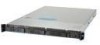
Figure 4. Front Panel Feature Overview
A
Slim-line drive bay (CDROM or DVD/CDR or Floppy)
B
Control Panel
C
Hard Drive Fault/Activity LED
D
1” Hard Drive Bays
E
Chassis Handle
1.6
Control Panel
The Server Chassis SC1400UP control panel assembly is pre-assembled and modular in
design. The entire module assembly slides into a predefined slot in the front of the chassis.
Figure 5. Control Panel Module