| Section |
Page |
| Intel® Server System SR1630BC Service Guide |
5 |
| About this Manual |
5 |
| Manual Organization |
5 |
| Product Contents |
6 |
| Intel® Server System SR1630BC - Product Contents |
6 |
| Note: You may need or want to purchase one or more of the following items for your server: |
6 |
| Safety Information |
9 |
| Important Safety Instructions |
9 |
| Wichtige Sicherheitshinweise |
9 |
| Consignes de sécurité |
9 |
| Instrucciones de seguridad importantes |
9 |
| Warnings |
11 |
| Table of Contents |
13 |
| List of Figures |
19 |
| List of Tables |
21 |
| 1 Server System References |
23 |
| 2 Server System Features |
25 |
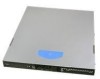
| Figure 1. Intel® Server System SR1630BC |
25 |
| Cable Routing |
27 |
| Figure 2. Cable Routing Drawing |
28 |
| Chassis Component Identification |
29 |
| Internal Components |
29 |
| A. Rack handles (two) |
29 |
| B. Processor air duct |
29 |
| C. System memory DIMM sockets |
29 |
| D. PCI add-in card bracket |
29 |
| E. Power supply |
29 |
| F. CPU Heatsink (two) |
29 |
| G. System blower fans (two) |
29 |
| H. Hard drives (two) |
29 |
| I. Control panel |
29 |
| J. Slimline optical drive |
29 |
| Figure 3. System Components |
29 |
| Server Board Connector and Component Locations |
30 |
| A. SATA 3 |
30 |
| B. Internal dual port USB2.0 header |
30 |
| C. SATA 5 |
30 |
| D. SATA 4 |
30 |
| E. Slot 3, PCI Express* x4 |
30 |
| F. Slot 4, 32-bit/33 MHz PCI |
30 |
| G. Intel® RMM3 slot |
30 |
| H. Slot 5, PCI Express* x8 |
30 |
| I. Slot 6, PCI Express* x8 (Riser card) |
30 |
| J. Slot 7, PCI Express* x8 |
30 |
| K. Black panel I / O ports |
30 |
| L. Diagnostic LEDs |
30 |
| M. Status LED |
30 |
| N. ID LED |
30 |
| O. External Serial B header |
30 |
| P. SATA Key |
30 |
| Q. System fan 3 header |
30 |
| R. Main power connector |
30 |
| S. DIMM sockets off Processor 1 socket (Channel A, B) |
30 |
| T. Power Supply Auxiliary Connector |
30 |
| U. SSI 24-pin Front Panel connector |
30 |
| V. System fan 2 header |
30 |
| W. CPU 1 fan header |
30 |
| X. CPU Power Connector |
30 |
| Y. CPU Socket 1 |
30 |
| Z. Intel® 5500 Chipset |
30 |
| AA. CPU Socket 2 |
30 |
| BB. CPU 2 fan header |
30 |
| CC. System fan 1 header |
30 |
| DD. DIMM sockets off Processor 2 socket (Channel D, E) |
30 |
| EE. SATA SGPIO |
30 |
| FF. SATA 0 |
30 |
| GG. SATA 1 |
30 |
| HH. SATA 2 |
30 |
| Figure 4. Server Board Connector and Component Locations |
30 |
| Configuration Jumpers |
31 |
| Figure 5. Configuration Jumper Location |
32 |
| Intel® Light Guided Diagnostics |
33 |
| Figure 6. Light Guided Diagnostic LEDs |
34 |
| A. POST Code Diagnostic LEDs |
34 |
| B. Status LED |
34 |
| C. System ID LED |
34 |
| D. HDD LED |
34 |
| E. System Fan 3 Fault LED |
34 |
| F. 5 VSB LED |
34 |
| G. DIMM Fault LED |
34 |
| H. System Fan 2 Fault LED |
34 |
| I. CPU 1 Fan Fault LED |
34 |
| J. CPU 2 Fan Fault LED |
34 |
| K. System Fan 1 Fault LED |
34 |
| L. DIMM Fault LED |
34 |
| Back Panel Connectors |
35 |
| A. Serial Port A |
35 |
| B. Video |
35 |
| C. USB Port 6-7 |
35 |
| D. USB Port 8-9 |
35 |
| E. NIC Port 1 |
35 |
| F. NIC Port 2 |
35 |
| Figure 7. Back Panel Connectors |
35 |
| RAID Support |
36 |
| Note: For AHCI capability in EFI, the AHCI legacy Option ROM should be set to “disabled”. |
36 |
| Front of Server System |
37 |
| Standard Control Panel |
37 |
| A. |
37 |
| B. |
37 |
| C. |
37 |
| D. |
37 |
| E. |
37 |
| F. |
37 |
| G. |
37 |
| Figure 8. Front Control Panel - Intel® Server System SR1630BC |
37 |
| Bezels |
38 |
| Rear of Server System |
39 |
| A. AC Power Connector |
39 |
| B. Serial Port A |
39 |
| C. Video Connector |
39 |
| D. NIC 1 Connector (10 / 100 / 1000 Mb) |
39 |
| E. NIC 2 Connector (10 / 100 / 1000 Mb) |
39 |
| F. USB Ports 6 and 7 |
39 |
| G. USB Ports 8 and 9 |
39 |
| H. PCI Express* Slot |
39 |
| Figure 9. Server System I/O Connector Locations |
39 |
| Peripheral Devices |
40 |
| A. Slimline optical drive bay |
40 |
| B. Hard drive bay HDD0 (located under the slimline optical drive bay) |
40 |
| C. Hard drive bay HDD1 |
40 |
| Figure 10. Optional Peripherals |
40 |
| Hard Disk Drives |
40 |
| Slimline Optical Drive Carrier |
41 |
| Rack-Mounted Systems |
41 |
| Hardware Requirements |
41 |
| Processor |
41 |
| Memory |
42 |
| Figure 11. DIMM Configuration Diagram |
42 |
| Figure 12. Channel Slots Configuration |
43 |
| Memory Sparing and Mirroring |
43 |
| Power Supply |
44 |
| Optional Hardware |
44 |
| Intel® RAID Activation Key |
44 |
| Hard Disk Drives |
44 |
| Note: The Intel® Remote Management Module 3 will not be supported in the Intel® Server System SR1630BC system. |
44 |
| 3 Hardware Installations and Upgrades |
45 |
| Before You Begin |
45 |
| Note: Whenever you service the system, you must first power down the server and unplug all peripheral devices and the AC power cord. |
45 |
| Tools and Supplies Needed |
45 |
| System References |
45 |
| Removing and Installing the Front Bezel |
45 |
| Removing the Front Bezel |
46 |
| Figure 13. Removing the Front Bezel |
46 |
| Installing the Front Bezel |
46 |
| Figure 14. Installing the Front Bezel |
46 |
| Removing and Installing the System Cover |
47 |
| Removing the System Cover |
47 |
| Note: You may need a non-skid surface or a stop behind the server system to prevent the server system from sliding on your work surface. |
47 |
| 1. Remove the top cover screw (see letter “A”). |
47 |
| 2. Remove the two screws at the front of the chassis (see letter “A” in the following figure). |
47 |
| 3. Loosen the screw at the rear of the chassis (see letter “B”). |
47 |
| 4. Push rearward on the blue grip point at the front of the server. |
47 |
| 5. Slide the cover back until it stops and then lift the cover upward to remove it. See letter “C”. |
47 |
| 6. Slide the cover back until it stops and lift the cover upward to remove it (see letter “B”). |
47 |
| Figure 15. Removing the Server System Cover |
47 |
| Installing the System Cover |
47 |
| 1. Observe the safety and ESD precautions at the beginning of this book. See “Safety Information” on page -ix. |
47 |
| 2. Place the cover over the server system so that the side edges of the cover sit just inside the server system sidewalls. Slide the cover forward (see letter “A” in Figure 16). |
48 |
| 3. Tighten the screw at the rear of the server (see letter “B”) and install the two screws at the front of the server (see letter “C”). |
48 |
| Figure 16. Installing the Server System Cover |
48 |
| Removing and Installing the Processor Air Duct |
48 |
| Removing the Processor Air Duct |
48 |
| 1. Observe the safety and ESD precautions at the beginning of this book. See “Safety Information”. |
48 |
| 2. Power down the server and unplug all peripheral devices and the AC power cable. |
48 |
| 3. Remove the server system cover. For instructions, see “Removing the System Cover”. |
48 |
| 4. Lift the processor air duct from its location behind the two system blower fans. |
48 |
| 5. Lift the processor air duct from its location over the two processor sockets. |
49 |
| Figure 17. Removing the Processor Air Duct |
49 |
| Installing the Processor Air Duct |
49 |
| 1. Observe the safety and ESD precautions at the beginning of this book. See “Safety Information”. |
49 |
| 2. Power down the server and unplug all peripheral devices and the AC power cable. |
49 |
| 3. Remove the server system cover. For instructions, see “Removing the System Cover”. |
49 |
| 4. Lower the air duct into place; insert the two hooks at the front of the processor air duct into the corresponding slots on th... |
49 |
| Figure 18. Installing the Processor Air Duct |
50 |
| Installing and Removing Memory |
50 |
| Installing DIMMs |
50 |
| 1. Observe the safety and ESD precautions at the beginning of this book. |
50 |
| 2. Turn off all peripheral devices connected to the server. |
50 |
| 3. Turn off the server. |
50 |
| 4. Disconnect the AC power cord from the server. |
50 |
| 5. Remove the cover from the server and locate the DIMM sockets (see “Installing the Memory”). |
50 |
| Figure 19. Installing the Memory |
51 |
| 6. Make sure the clips at either end of the DIMM socket(s) are pushed outward to the open position (see letter “A” in Figure 19). |
51 |
| 7. Holding the DIMM by the edges, remove it from its anti-static package. |
51 |
| 8. Position the DIMM above the socket. Align the two small notches in the bottom edge of the DIMM with the keys in the socket (see letter “B” in Figure 19). |
51 |
| 9. Insert the bottom edge of the DIMM into the socket (see letter “C” in Figure 19). |
51 |
| 10. When the DIMM is inserted, push down on the top edge of the DIMM until the retaining clips snap into place (see letter “D” in Figure 19). Make sure the clips are firmly in place (see letter “E” in Figure 19). |
51 |
| 11. Replace the server’s cover and reconnect the AC power cord. |
51 |
| Removing DIMMs |
51 |
| 1. Observe the safety and ESD precautions at the beginning of this book. |
51 |
| 2. Turn off all peripheral devices connected to the server. Turn off the server. |
51 |
| 3. Remove the AC power cord from the server. |
51 |
| 4. Remove the server's cover. |
51 |
| 5. Gently spread the retaining clips at each end of the socket. The DIMM lifts from the socket. |
51 |
| 6. Holding the DIMM by the edges, lift it from the socket, and store it in an anti-static package. |
51 |
| 7. Reinstall and reconnect any parts you removed or disconnected to reach the DIMM sockets. |
52 |
| 8. Replace the server's cover and reconnect the AC power cord. |
52 |
| Installing or Replacing the Processor |
53 |
| Note: Use the following instructions to install or replace a processor instead of using the instructions that came with the processor. |
53 |
| Caution: Processor must be appropriate: If you install a processor that is inappropriate for your server, you may damage the server board. See “Server System References” for a link to the list of compatible processor(s). |
53 |
| ESD and handling processors: Reduce the risk of electrostatic discharge (ESD) damage to the processor by doing the following: (1... |
53 |
| Installing the Processor |
53 |
| 1. Observe the safety and ESD precautions at the beginning of this book. See “Safety Information” for more information. |
53 |
| 2. Turn off all peripheral devices connected to the server and turn off the server. |
53 |
| 3. Disconnect the AC power cord from the server. |
53 |
| 4. Remove the server's cover. See the document that came with your server chassis for instructions on removing the server's cover. |
53 |
| 5. Locate the processor socket and open the socket lever (see Figure 20). |
53 |
| Figure 20. Lifting the Load Lever |
53 |
| 6. Open the load plate (see letter “A” in Figure 20 and letter “B” in Figure 21). |
53 |
| Figure 21. Open the Load Plate |
54 |
| 7. Remove the socket protective cover (see Figure 22). |
54 |
| Figure 22. Remove the Socket Protective Cover |
54 |
| 8. Take the processor out of the box and remove the protective shipping cover (Figure 23). |
54 |
| Figure 23. Remove the Processor Protective Cover |
54 |
| 9. Align the processor cutouts to match the two socket pins, and then insert the processor into the socket as shown in Figure 24. |
55 |
| Figure 24. Installing the Processor |
55 |
| 10. Close the load plate (see the letter “A” in Figure 25), close the socket lever and ensure the load plate tab engages under the socket lever when fully closed. (See letter “B” and “C” in Figure 25) |
55 |
| Figure 25. Close the Load Plate and Socket Lever |
55 |
| Note: Make sure the alignment triangle mark and the alignment triangle cutout align correctly. To assist in package orientation and alignment with the socket: |
55 |
| Installing the Heat Sink(s) |
56 |
| Figure 26. Protective Film Removal |
56 |
| 1. If a protective film covers the thermal interface material (TIM) on the underside of the heat sink, remove the protective film. |
56 |
| 2. Align heat sink fans to the front and back of the chassis for correct airflow. Airflow goes from front-to-back of chassis. |
56 |
| 3. Each heat sink has four captive fasteners and should be tightened as shown. |
56 |
| 4. Using a #2 Phillips* screwdriver, finger-tighten each fastener diagonally according to the white-circled numbers (see Figure 27). |
56 |
| 5. Securely re-tighten each fastener again in the same order as performed in Step 4. |
56 |
| 6. Attach fan power cable to server board as shown. |
56 |
| Figure 27. IU Reference Heat sink Assembly |
57 |
| 7. Reinstall and reconnect any parts you removed or disconnected to reach the processor sockets. |
57 |
| 8. Replace the server’s cover and reconnect the AC power cord. See the docmentation that came with your server chassis for instructions on installing the server’s cover. |
57 |
| Replacing a Processor |
57 |
| 1. Observe the safety and ESD precautions at the beginning of this book. |
57 |
| 2. Turn off all peripheral devices connected to the server. Turn off the server. |
57 |
| 3. Remove the AC power cord from the server. |
57 |
| 4. Remove the server's cover. |
57 |
| 5. Unplug the processor fan cable from the server board. |
57 |
| 6. Loosen the four captive screws on the corners of the heat sink. |
57 |
| 7. Twist the heat sink slightly to break the seal between the heat sink and the processor. |
57 |
| 8. Lift the heat sink from the processor. If it does not pull up easily, twist the heat sink again. Do not force the heat sink from the processor. Doing so could damage the processor. |
57 |
| 9. Lift the processor lever. |
57 |
| 10. Raise the CPU load plate. |
57 |
| 11. Remove the processor. |
58 |
| 12. If installing a replacement processor, see “Installing the Processor”. Otherwise, install the protective socket cover over the empty processor socket and reinstall the chassis cover. |
58 |
| Installing and Removing a Fixed Hard Drive |
58 |
| Caution: Fixed mount hard drives are NOT hot-swappable. Before removing or replacing the drive, you must first take the server o... |
58 |
| Installing and Removing a Hard Disk Drive |
58 |
| Caution: The hard drives are NOT hot swappable. Before removing or replacing a hard drive, you must first take the server out of... |
58 |
| You can install up to two SATA drives. The HDD0 drive bay is at the left side of the chassis, underneath the optional CD-ROM dri... |
58 |
| Note: The server system does not support all hard drives. See “Server System References” for a link to a list of supported hardware. |
58 |
| 1. Locate the drive position you want to use. |
58 |
| Figure 28. Locating Drive Positions |
59 |
| 2. HDD1 location only: Slide the power cables from the cable clip that is located on the top of the hard drive carrier. |
59 |
| 3. Remove the screw that secures the hard drive bracket to the chassis (see letter \ |
59 |
| Figure 29. Removing Drive Carrier from Server System |
60 |
| 4. Position the drive with the drive connectors facing up, as shown in the following figure (Figure 30). Set the drive carrier o... |
60 |
| Figure 30. Installing Drive into the Drive Carrier |
60 |
| 5. Set the drive assembly into place in the chassis. See letter \ |
61 |
| 6. Attach the drive assembly to the chassis with the screw you removed previously in step 3 (see letter \ |
61 |
| Note: You must install the assembly that contains the optical drive bracket on the left side of the system. |
61 |
| Figure 31. Installing Drive Assembly into the Server System |
61 |
| 7. HDD1 only: Route the power cable into the cable clip on the top of the hard drive bracket. |
61 |
| 8. Connect the data cables to the drive(s). |
61 |
| a. If a drive is installed in the HDD0 carrier, connect the HDD0 data cable to the SATA 0 connector on the server board. See letter \ |
61 |
| b. If a drive is installed in the HDD1 carrier, connect the HDD1 data cable to the SATA 1 connector on the server board. See letter \ |
61 |
| Note: The data cables are factory routed underneath the fan module. Use caution to make sure you connect the cables between the server board and the hard drives. The cables are labeled at each end. |
61 |
| 9. Connect the power cables to the drive(s): |
61 |
| a. If a drive is installed in the HDD1 carrier, attach the connector on the daisy chain power cable that is closest to the power supply to the HDD1 connector. |
61 |
| a. If a drive is installed in the HDD0 carrier, attach the middle connector on the daisy chain power cable to the HDD0 power connector. |
62 |
| Figure 32. Connecting Hard Driver Power and Data Cables |
62 |
| Removing a Fixed Hard Disk Drive |
62 |
| 1. Disconnect the power and data cables from the drive. |
62 |
| 2. HDD1 location only: Slide the power cable from the cable clip that is located on the top of the hard drive carrier. |
62 |
| 3. Remove the screw that holds the hard drive bracket to the chassis (see letter \ |
62 |
| Figure 33. Removing Drive Carrier from the Server System |
63 |
| 4. Remove the four screws that attach the hard drive to the drive carrier. Lift the drive from the carrier. Store the drive in an anti-static bag. |
63 |
| 5. If you are installing a new drive, skip the rest of these steps and instead see “Installing and Removing a Fixed Hard Drive”. |
63 |
| 6. Insert the screws that held the drive in the carrier into the screw locations on the carrier for future use. |
63 |
| 7. Set the drive assembly into place in the chassis (see letter \ |
63 |
| Note: You must install the assembly that contains the optical drive bracket on the left side of the system. |
63 |
| Installing or Removing a Slimline Optical Drive |
63 |
| Caution: Slimline optical drives are NOT hot-swappable. Before removing or replacing the drive, you must first take the server o... |
63 |
| To maintain proper system cooling, if you do not install a device at this location, you must install the provided filler blank. |
64 |
| Installing a Slimline Optical Drive |
64 |
| Note: The hardware necessary to install your optical drive was shipped to you in a bag labeled “CD-ROM Assy”. |
64 |
| 1. First time installation only: Remove the knockout in the bezel that corresponds to the opening for the optical drive by rocki... |
64 |
| Figure 34. Removing the Knockout in Bezel for Optical Opening |
64 |
| 2. Attach the brackets to the optical drive using the four screws as shown in the following figure. |
64 |
| Figure 35. Attaching the Brackets to the Optical Drive |
65 |
| 3. Slide the optical drive assembly in through the front of the chassis, as shown by letter \ |
65 |
| Figure 36. Installing the Optical Drive into the Server System |
65 |
| Removing a Slimline Optical Drive |
66 |
| 1. Remove the power and data cables. |
66 |
| 2. Remove the screws and slide the optical drive assembly out of the chassis. |
66 |
| Figure 37. Removing the Slimline Optical Drive Assembly from the Server System |
66 |
| 3. Remove the four screws from the brackets. |
66 |
| Figure 38. Removing the Brackets from the Slimline Optical Drive Assembly |
66 |
| Installing and Removing the PCI Riser Assembly |
67 |
| Removing the PCI Riser Assembly |
67 |
| 1. Disconnect any cables attached to any add-in cards. |
67 |
| 2. Grasp the riser assembly and pull up to release it from the system. |
67 |
| Figure 39. Removing the PCI Riser Assembly from the Server System |
67 |
| Installing the PCI Riser Assembly |
67 |
| 1. Lower the riser assembly into place (see letter \ |
67 |
| 2. Align the two hooks in the riser assembly with the matching slots at the back of the server system (see letter \ |
67 |
| Figure 40. Installing the PCI Riser Assembly |
68 |
| 3. Press down uniformly until the two hooks on the rear of the PCI riser assembly engage the server system back panel slots. The riser card will seat into the matching socket on the server board. Ensure the riser card is fully seated. |
68 |
| Installing and Removing a PCI Add-In Card |
68 |
| Installing a PCI Add-In Card |
68 |
| 1. After removing the PCI riser assembly from the server system, remove the screw that attaches the PCI bracket shield to the rear of the chassis to remove the shield. Retain the screw. |
68 |
| 2. Insert the PCI card edge connector in the slot on the PCI riser. |
68 |
| Figure 41. Installing the PCI Riser Assembly from the Server System |
69 |
| Figure 42. Installing a PCI Card in a Riser Card |
69 |
| 3. Insert the riser card with the attached PCI card into the PCI slot on the server board. Press firmly on the riser card until it is fully seated. Be sure to press down on the riser card, not on the PCI card. |
69 |
| Caution: Press the riser card straight down into the slot. Tipping the riser card while installing into the slot may damage the riser card or slot on the server board. |
69 |
| 4. Use the screw removed in step 1 to secure the riser card assembly to the chassis. |
69 |
| Removing a PCI Add-In Card |
69 |
| 1. Remove the screw holding the add-in card in place (see letter \ |
69 |
| 2. Remove the PCI add-in card from the riser card connector (see letter \ |
69 |
| Figure 43. Removing a PCI Card in a Riser Card |
70 |
| Removing and Installing the System Blowers |
70 |
| Note: The fans that are integrated into the power supply cannot be replaced separately. If one of the fans in the power supply fails, you must replace the power supply. |
70 |
| Replacing the System Blower |
70 |
| 1. Remove the processor air duct. For instructions, see “Removing the Processor Air Duct”. |
70 |
| 2. Disconnect the two system blower cables from the server board. See letters \ |
71 |
| Figure 44. Disconnecting the System Blower Cables |
71 |
| 3. Remove the two screws that secure the fan bracket in place. Save these screws. You will re-install them later (see letter \ |
71 |
| 4. Remove the fan cable from beneath the clip at the front of the fan bracket (see letter \ |
71 |
| 5. Lift the fan bracket from the server. Lift the bracket at an angle, with the front of the bracket first, to clear the hard disk drive brackets (see letter \ |
72 |
| Figure 45. Removing the Blower Bracket from the Server System |
72 |
| 6. Turn the bracket over and remove the two screws that attach the failed fan to the fan bracket. Save these screws. You will reinstall them later. See letter \ |
72 |
| Figure 46. Removing the System Blowers from the Bracket |
72 |
| 7. Install the replacement blower onto the bracket, using the two screws you removed previously in step 3. |
73 |
| 8. Set the blower assembly into the system. Insert the rear edge first and push the assembly slightly rearward to clear the hard disk drive brackets. Use caution to make sure you do not pinch any cables. |
73 |
| 9. Route the cable from the blower at the right around the right side of the assembly and under the clip at the front of the blower bracket. |
73 |
| 10. Secure the blower assembly to the system using the two screws you removed previously. |
73 |
| 11. Connect the blower cables to the server board. See letters \ |
73 |
| Figure 47. Connecting the System Blower Cables |
73 |
| Replacing the Server Board |
74 |
| Removing the Server Board |
74 |
| 1. Remove the CPU air duct and air baffle. |
74 |
| 2. If installed, remove the memory, processor heat sinks, and processors from the server. |
74 |
| 3. If installed, remove the PCI riser assembly. |
74 |
| 4. If installed, disconnect all SATA cables from the server board. |
74 |
| 5. Remove the system PCI fan and blower cables. |
74 |
| 6. Disconnect all power cables coming from the power supply to the server board. |
74 |
| 7. Remove the seven screws from the server board (see letter \ |
74 |
| Figure 48. Removing the Server Board |
74 |
| 8. Install the replacement server board. See “Installing the Server Board” on page -53. |
74 |
| Installing the Server Board |
75 |
| 1. Place the server board into the server system as shown in the following figure (see letter \ |
75 |
| 2. Attach the server board with seven screws (see letter \ |
75 |
| Figure 49. Installing the Server Board |
75 |
| 3. Re-connect all power cables coming from the power supply to the server board. |
75 |
| 4. Re-connect the PCI Fan and blower cables. |
75 |
| 5. Re-connect all SATA cables to the server board. |
75 |
| 6. Install the PCI riser assembly. |
75 |
| 7. Install the memory, processor heat sinks, and processors. |
75 |
| 8. Install the CPU air duct and air baffle. |
75 |
| Replacing the Backup Battery |
76 |
| Warning: Danger of explosion if battery is incorrectly replaced. Replace only with the same or equivalent type recommended by the equipment manufacturer. Discard used batteries according to manufacturer's instructions. |
76 |
| Advarsel: Lithiumbatteri - Eksplosionsfare ved fejlagtig håndtering. Udskiftning må kun ske med batteri af samme fabrikat og type. Levér det brugte batteri tilbage til leverandøren. |
76 |
| Advarsel: Lithiumbatteri - Eksplosjonsfare. Ved utskifting benyttes kun batteri som anbefalt av apparatfabrikanten. Brukt batteri returneres apparatleverandøren. |
76 |
| Varning: Explosionsfara vid felaktigt batteribyte. Använd samma batterityp eller en ekvivalent typ som rekommenderas av apparattillverkaren. Kassera använt batteri enligt fabrikantens instruktion. |
76 |
| Varoitus: Paristo voi räjähtää, jos se on virheellisesti asennettu. Vaihda paristo ainoastaan laitevalmistajan suosittelemaan tyyppiin. Hävitä käytetty paristo valmistajan ohjeiden mukaisesti. |
76 |
| 1. Observe the safety and ESD precautions at the beginning of this book. |
77 |
| 2. Turn off all peripheral devices connected to the server. Turn off the server. |
77 |
| 3. Disconnect the AC power cord from the server. |
77 |
| 4. Remove the server's cover and locate the battery. |
77 |
| 5. Insert the tip of a small flat bladed screwdriver, or an equivalent, under the tab in the plastic retainer. Gently push down on the screwdriver to lift the battery. |
77 |
| 6. Remove the battery from its socket. |
77 |
| Figure 50. Replacing the Backup Battery |
77 |
| 7. Dispose of the battery according to local ordinance. |
77 |
| 8. Remove the new lithium battery from its package, and, being careful to observe the correct polarity, insert it in the battery socket. |
77 |
| 9. Close the chassis. |
77 |
| 10. Run Setup to restore the configuration settings to the RTC. |
77 |
| Replacing the Power Supply |
77 |
| Caution: The power supply is not hot-swappable. Before removing or replacing the power supply, you must first take the server ou... |
77 |
| Removing the Power Supply |
77 |
| 1. Disconnect all power supply cables including power at rear of chassis (see letter “A”). |
78 |
| 2. Remove the two screws securing the power supply to the back panel (see letter “B”). |
78 |
| 3. Lift the power supply up to clear the chassis tab (see letter “C”) and remove the power supply by sliding it out (see letter “D”). |
78 |
| Figure 51. Removing the Power Supply from the Server System |
78 |
| Installing the Power Supply |
78 |
| 1. Insert the replacement power supply by first engaging the back panel (see letter “A”). |
78 |
| 2. Lower the front of the power supply into place behind the chassis tab (see letter “B”). |
79 |
| Figure 52. Installing the Power Supply into the Server System |
79 |
| 3. Secure the power supply to the back panel with two screws (see letter “C”). |
79 |
| 4. Connect all cables, including the power at the rear of the chassis (see letter “D”). |
79 |
| Installing and Removing the Rack Handles |
79 |
| Installing the Rack Handles |
79 |
| 1. Align the rack handle with the holes on the side of the server system and attach the rack handle with the two screws. |
79 |
| Figure 53. Installing the Rack Handle |
80 |
| 2. Repeat step 1 on the opposite side of the server. |
80 |
| Removing the Rack Handles |
81 |
| 1. Remove the two screws holding the rack handle in place, and remove the rack handle from the server system. |
81 |
| Figure 54. Removing the Rack Handle |
81 |
| 4 Server Utilities |
83 |
| Using the BIOS Setup Utility |
83 |
| Starting Setup |
83 |
| If You Cannot Access Setup |
83 |
| Setup Menus |
83 |
| Upgrading the BIOS |
85 |
| Preparing for the Upgrade |
85 |
| Recording the Current BIOS Settings |
85 |
| 1. Boot the computer and press <F2> when you see the message: |
85 |
| 2. Write down the current settings in the BIOS Setup program. |
85 |
| Note: Do not skip step 2. You need these settings to configure your server at the end of the procedure. |
85 |
| Obtaining the Upgrade |
86 |
| Note: Review the instructions and release notes provided in the readme file distributed with the BIOS image file before attempti... |
86 |
| Upgrading the BIOS |
86 |
| Caution: Do not power down the system during the BIOS update process! The system resets automatically when the BIOS upgrade process completes. Doing so may corrupt the system BIOS. |
86 |
| Note: You may encounter a CMOS Checksum error or other problem after reboot. If this happens, shut down the system and boot it again. CMOS checksum errors require that you enter Setup, check your settings, save your settings, and exit Setup. |
86 |
| Clearing the CMOS |
86 |
| 1. Power down the system; do not disconnect the AC power. |
86 |
| 2. Open the server. |
86 |
| 3. Move the jumper from the normal operation position, CMOS Clear by MBX, at pins 1 and 2 to the CMOS Clear Force Erase position, covering pins 2 and 3. |
86 |
| Figure 55. CMOS Recovery Jumper |
87 |
| 4. Reconnect the AC power and power up the system. |
87 |
| 5. When the system begins beeping, power it down and disconnect the AC power. |
87 |
| 6. Return the CMOS Clear jumper to the spare location, covering pins 1 and 2. |
87 |
| 7. Close the server chassis; reconnect the AC power and power up the system. |
87 |
| 8. The CMOS is now cleared and you can reset it by going into the BIOS setup. |
87 |
| Resetting the Password |
87 |
| 1. Power down the system and disconnect the AC power. |
87 |
| 2. Open the server chassis. |
87 |
| 3. Move the jumper from the normal operation position, Password Clear Protect, at pins 1 and 2 to the Password Clear Erase position, covering pins 2 and 3. |
87 |
| Figure 56. Password Recovery Jumper |
88 |
| 4. Reconnect the AC power; power up the system. |
88 |
| 5. Power down the system and disconnect the AC power. |
88 |
| 6. Return the Password Reset jumper to the Password Clear Protect position, covering pins 1 and 2. Reconnect AC power and power up the server. |
88 |
| 7. The password is now cleared and you can reset it by going into the BIOS setup. |
88 |
| Appendix A: Technical Reference |
89 |
| 400-W Single Power Supply Input Voltages |
89 |
| 400-W Single Power Supply Output Voltages |
89 |
| 1. Maximum continuous total DC output power should not exceed 400 W. |
89 |
| 2. Peak total DC output power should not exceed 450 W. |
89 |
| 3. Peak power and current loading is supported for a minimum of 12 seconds. |
89 |
| 4. Combined 3.3 V and 5 V power should not exceed 80 W. |
89 |
| System Environmental Specifications |
90 |
| Appendix B: Intel® Server Issue Report Form |
91 |
| Note: For the fastest service, please submit your form via the Internet. |
91 |
| Board / Chassis Information |
91 |
| DIMM Configuration |
92 |
| Operating System Information |
92 |
| Add-in Card, Peripheral, Video, NIC |
93 |
| Hard Drive Information |
94 |
| Management Information |
94 |
| Complete Problem Description |
94 |
| Appendix C: LED Decoder |
97 |
| Figure 57. Diagnostic LED Placement Diagram |
97 |
| A. Status LED |
97 |
| B. ID LED |
97 |
| C. Diagnostic LED #7 (MSB LED) |
97 |
| D. Diagnostic LED #6 |
97 |
| E. Diagnostic LED #5 |
97 |
| F. Diagnostic LED #4 |
97 |
| G. Diagnostic LED #3 |
97 |
| H. Diagnostic LED #2 |
97 |
| I. Diagnostic LED #1 |
97 |
| J. Diagnostic LED #0 (LSB LED) |
97 |
| Appendix D: Getting Help |
109 |
| 1. Visit the following Intel support web page: http://support.intel.com/support/motherboards/server |
109 |
| 2. If you are still unable to obtain a solution to your issue, send an email to Intel’s technical support center using the online form available at http://supportmail.intel.com/scripts-emf/welcome.aspx |
109 |
| 3. Lastly, you can contact an Intel support representative using one of the support phone numbers available at http://support.in... |
109 |
| Warranty Information |
109 |
| Appendix E: Regulatory and Compliance Information |
111 |
| Product Regulatory Compliance |
111 |
| Warning: To ensure regulatory compliance, you must adhere to the assembly instructions in this guide to ensure and maintain comp... |
111 |
| To help ensure EMC compliance with your local regional rules and regulations, before computer integration, make sure that the se... |
111 |
| This is an FCC Class A device. Integration of it into a Class B system does not result in a Class B device. |
111 |
| Product Safety Compliance |
111 |
| Intended Application |
111 |
| Product EMC Compliance - Class A Compliance |
112 |
| Note: Legally the product is required to comply with Class A emission requirements as it is intended for a commercial type market place. Intel targets 10db margin to Class A Limits |
112 |
| Certifications / Registrations / Declarations |
112 |
| Product Regulatory Compliance References |
113 |
| Electromagnetic Compatibility Notices |
116 |
| FCC Verification Statement (USA) |
116 |
| Industry Canada (ICES-003) |
117 |
| Europe (CE Declaration of Conformity) |
117 |
| VCCI (Japan) |
117 |
| BSMI (Taiwan) |
117 |
| Korean Compliance (RRL) |
118 |
| 1. Type of Equipment (Model Name): On License and Product |
118 |
| 2. Certification No.: On RRL certificate. Obtain certificate from local Intel representative |
118 |
| 3. Name of Certification Recipient: Intel Corporation |
118 |
| 4. Date of Manufacturer: Refer to date code on product |
118 |
| 5. Manufacturer/Nation: Intel Corporation/Refer to country of origin marked on product |
118 |
| CNCA (CCC-China) |
118 |
| Product Ecology Compliance |
118 |
| Other Markings |
121 |
| Regulated Specified Components |
122 |
| End-of-Life / Product Recycling |
123 |
| Appendix F: Warranty |
125 |
| Limited Warranty for Intel® Chassis Subassembly Products |
125 |
| Extent of Limited Warranty |
125 |
| Limitations of Liability |
126 |
| How to Obtain Warranty Service |
126 |
| Telephone Support |
127 |
| Returning a Defective Product |
127 |
| Appendix G: Installation/Assembly Safety Instructions |
129 |
| Important Safety Instructions |
129 |
| English |
129 |
| 1. Turn off all peripheral devices connected to the system. |
129 |
| 2. Turn off the system by pressing the power button. |
129 |
| 3. Unplug all AC power cords from the system or from wall outlets. |
129 |
| 4. Label and disconnect all cables connected to I/O connectors or ports on the back of the system. |
129 |
| 5. Provide some electrostatic discharge (ESD) protection by wearing an antistatic wrist strap attached to chassis ground of the system-any unpainted metal surface-when handling components. |
129 |
| 6. Do not operate the system with the chassis covers removed. |
129 |
| Wichtige Sicherheitshinweise |
130 |
| 1. Schalten Sie alle an Ihr System angeschlossenen Peripheriegeräte aus. |
130 |
| 2. Schalten Sie das System mit dem Hauptschalter aus. |
130 |
| 3. Ziehen Sie den Stromanschlußstecker Ihres Systems aus der Steckdose. |
130 |
| 4. Auf der Rückseite des Systems beschriften und ziehen Sie alle Anschlußkabel von den I/O Anschlüssen oder Ports ab. |
130 |
| 5. Tragen Sie ein geerdetes Antistatik Gelenkband, um elektrostatische Ladungen (ESD) über blanke Metallstellen bei der Handhabung der Komponenten zu vermeiden. |
130 |
| 6. Schalten Sie das System niemals ohne ordnungsgemäß montiertes Gehäuse ein. |
130 |
| Consignes de sécurité |
131 |
| 1. Mettez hors tension tous les périphériques connectés au système. |
131 |
| 2. Mettez le système hors tension en mettant l'interrupteur général en position OFF (bouton-poussoir). |
131 |
| 3. Débranchez tous les cordons d'alimentation c.a. du système et des prises murales. |
131 |
| 4. Identifiez et débranchez tous les câbles reliés aux connecteurs d'E-S ou aux accès derrière le système. |
131 |
| 5. Pour prévenir les décharges électrostatiques lorsque vous touchez aux composants, portez une bande antistatique pour poignet et reliez-la à la masse du système (toute surface métallique non peinte du boîtier). |
131 |
| 6. Ne faites pas fonctionner le système tandis que le boîtier est ouvert. |
131 |
| Instrucciones de seguridad importantes |
132 |
| 1. Apague todos los dispositivos periféricos conectados al sistema. |
132 |
| 2. Apague el sistema presionando el interruptor encendido/ apagado. |
132 |
| 3. Desconecte todos los cables de alimentación CA del sistema o de las tomas de corriente alterna. |
132 |
| 4. Identifique y desconecte todos los cables enchufados a los conectores E/S o a los puertos situados en la parte posterior del sistema. |
132 |
| 5. Cuando manipule los componentes, es importante protegerse contra la descarga electrostática (ESD). Puede hacerlo si utiliza una muñequera antiestática sujetada a la toma de tierra del chasis - o a cualquier tipo de superficie de metal sin pintar. |
132 |
| 6. No ponga en marcha el sistema si se han extraído las tapas del chasis. |
132 |
| Italiano |
133 |
| 1. Spegnere tutti i dispositivi periferici collegati al sistema. |
133 |
| 2. Spegnere il sistema, usando il pulsante spento/acceso dell'interruttore del sistema. |
133 |
| 3. Togliere tutte le spine dei cavi del sistema dalle prese elettriche. |
133 |
| 4. Identificare e sconnettere tutti i cavi attaccati ai collegamenti I/O od alle prese installate sul retro del sistema. |
133 |
| 5. Qualora si tocchino i componenti, proteggersi dallo scarico elettrostatico (SES), portando un cinghia anti-statica da polso che è attaccata alla presa a terra del telaio del sistema - qualsiasi superficie non dipinta - . |
133 |
| 6. Non far operare il sistema quando il telaio è senza le coperture. |
133 |
| Appendix H: Safety Information |
135 |
| English |
135 |
| Server Safety Information |
135 |
| Safety Warnings and Cautions |
135 |
| Intended Application Uses |
136 |
| Site Selection |
136 |
| Equipment Handling Practices |
136 |
| Deutsch |
137 |
| Sicherheitshinweise für den Server |
137 |
| Sicherheitshinweise und Vorsichtsmaßnahmen |
137 |
| Zielbenutzer der Anwendung |
138 |
| Standortauswahl |
138 |
| Handhabung von Geräten |
138 |
| Warnungen zu Netzspannung und Elektrizität |
139 |
| Caution: Durch Betätigen der mit dem Standby-Symbol gekennzeichneten Netztaste wird das System NICHT vollständig vom Netz getren... |
139 |
| Nehmen Sie keine Änderungen am Netzkabel vor, und verwenden Sie kein Kabel, das nicht genau dem geforderten Typ entspricht. Jedes Netzteil im System muß über ein eigenes Netzkabel angeschlossen werden. |
139 |
| Einige Netzteile von Intel Servern verwenden Nullleitersicherungen. Vorsicht ist geboten im Umgang mit Netzteilen, welche Nullleitersicherungen verwenden, um das Risiko eines elektrischen Schlages zu vermeiden |
139 |
| Das Netzteil in diesem Produkt enthält keine Teile, die vom Benutzer gewartet werden können. Öffnen Sie das Netzteil nicht. Im N... |
139 |
| Wenn Sie ein hot-plug-fähiges Netzteil austauschen, ziehen Sie dessen Netzkabel ab, bevor Sie es aus dem Server ausbauen. |
139 |
| Zur Vermeidung von Stromschlägen schalten Sie den Server aus, und trennen Sie vor dem Öffnen des Geräts das Netzkabel sowie alle an den Server angeschlossene Telekommunikationssysteme, Netzwerke und Modems. |
139 |
| Hinweis für Netzkabel |
139 |
| Caution: Prüfen Sie zur Vermeidung von Stromschlag oder Feuergefahr die mit dem Produkt zu verwendenden Netzkabel wie folgt: |
139 |
| Warnhinweise für den Systemzugang |
140 |
| Caution: Um Verletzungen und Beschädigungen zu vermeiden, sollten Sie vor Arbeiten im Produktinneren folgende Sicherheitsanweisungen beachten: |
140 |
| Warnhinweise für Racks |
140 |
| Elektrostatische Entladungen (ESD) |
141 |
| Caution: Elektrostatische Entladungen können zur Beschädigung von Festplatten, Platinen und anderen Komponenten führen. Daher so... |
141 |
| Gehen Sie bei der Handhabung von Platinen immer mit größter Vorsicht vor. Sie können äußerst empfindlich gegenüber elektrostatis... |
141 |
| Andere Gefahren |
141 |
| Batterieaustausch |
141 |
| Caution: Wird die Batterie unsachgemäß ausgetauscht, besteht Explosionsgefahr. Verwenden Sie als Ersatz nur die vom Gerätehersteller empfohlene Batterie. |
141 |
| Beachten Sie bei der Entsorgung von Batterien die gültigen Bestimmungen. |
141 |
| Versuchen Sie nicht, eine Batterie aufzuladen. |
141 |
| Versuchen Sie nicht, eine Batterie zu öffnen oder sonstwie zu beschädigen. |
141 |
| Kühlung und Luftstrom |
141 |
| Caution: Verlegen Sie Kabel sorgfältig entsprechend der Anleitung, um Störungen des Luftstroms und Kühlungsprobleme zu vermeiden. |
141 |
| Laser-Peripheriegeräte oder -Komponenten |
142 |
| Caution: Beachten Sie zur Vermeidung von Strahlung und Verletzungen die folgenden Hinweise: |
142 |
| Français |
142 |
| Consignes de securite sur le serveur |
142 |
| Séurité: avertissements et mises en garde |
142 |
| Domaines d’utilisation prévus |
143 |
| Sélection d’un emplacement |
143 |
| Pratiques de manipulation de l’équipement |
144 |
| Alimentation et avertissements en matiére d’électricité |
144 |
| Les alimentations de certains serveurs Intel sont munies de doubles fusibles pôle/neutre: veuillez observer les précautions d'usage afin d'éviter tout risque d'eléctrocution. |
144 |
| N’essayez pas de modifier ou d’utiliser un cordon d’alimentation secteur s’il ne s’agit pas du type exact requis. Un cordon secteur est requis pour chaque alimentation système. |
144 |
| Le bloc d’alimentation de ce produit ne contient aucun composant réparable par l’utilisateur. N’ouvrez pas le bloc d’alimentatio... |
144 |
| Lorsque vous remplacez un bloc d’alimentation à chaud, débranchez le cordon du bloc d’alimentation en cours de remplacement avant de le retirer du serveur. |
145 |
| Pour éviter tout risque d’électrocution, mettez le système hors tension et débranchez les cordons d’alimentation ainsi que les systèmes de télécommunication, réseaux et modems reliés au système avant d’ouvrir ce dernier. |
145 |
| Avertissements sur le cordon d’alimentation |
145 |
| Avertissements sur l’accés au systéme |
145 |
| Avertissements sur le montage en rack |
146 |
| Décharges électrostatiques (ESD) |
147 |
| Manipulez toujours les cartes avec précaution. Elles peuvent être extrêmement sensibles aux ESD. Ne tenez les cartes que par leu... |
147 |
| Autres risques |
147 |
| Remplacement de la pile |
147 |
| Mettez la pile au rebut en vous conformant aux réglementations locales. |
147 |
| N’essayez pas de recharger une pile. |
147 |
| N’essayez pas de démonter, de percer ou d’endommager la pile d’une quelconque façon. |
147 |
| Refroidissement et ventilation |
147 |
| Périphériques laser |
148 |
| Español |
148 |
| Información de seguridad del servidor |
148 |
| Advertencias y precauciones sobre seguridad |
148 |
| Aplicaciones y usos previstos |
149 |
| Seleccién de la ubicación |
149 |
| Manipulacién del equipo |
150 |
| Advertencias de alimentacién y eléctricas |
150 |
| Algunas fuentes de alimentación de electricidad de los servidores de Intel utilizan el polo neutral del fuselaje. Para evitar ri... |
150 |
| No intente modificar ni utilizar un cable de alimentación de CA si no es del tipo exacto requerido. Se necesita un cable de CA para cada fuente de alimentación del sistema. |
150 |
| La fuente de alimentación de este producto no contiene piezas que puedan ser reparadas por el usuario. No abra la fuente de alim... |
150 |
| Al reemplazar una fuente de alimentación de conexión en funcionamiento, desenchufe el cable de alimentación de la fuente de alimentación que va a reemplazar antes de extraerla del servidor. |
150 |
| Para evitar el riesgo de descargas eléctricas, antes de abrir el servidor, apáguelo, desconecte el cable de alimentación, los sistemas de telecomunicaciones, las redes y los módems conectados al mismo. |
150 |
| Advertencias sobre el cable de alimentación |
150 |
| Advertencias el acceso al sistema |
151 |
| Advertencias sobre el montaje en bastidor |
152 |
| Descarga electrostática (ESD) |
153 |
| Manipule siempre las tarjetas con el máximo cuidado. Pueden ser sumamente sensibles a las descargas electrostáticas. Sujételas s... |
153 |
| Otros riesgos |
153 |
| Sustitución de la batería |
153 |
| Deseche las baterías respetando la normativa local. |
153 |
| No intente recargar la batería. |
153 |
| No intente desmontar, pinchar o causar cualquier otro desperfecto a una batería. |
153 |
| Enfriamiento y circulación de aire |
154 |
| Para conseguir una refrigeración y corriente de aire adecuadas, compruebe que cuando sistema esté funcionando, las cubiertas de ... |
154 |
| Periféricos o dispositivos láser |
154 |
 1
1 18
18 19
19 20
20 21
21 22
22 23
23 24
24 25
25 26
26 27
27 28
28

