Intel SRCSASBB8I Hardware User Guide - Page 17
Intel® RAID Controller SRCSASBB8I Characteristics
 |
UPC - 735858201346
View all Intel SRCSASBB8I manuals
Add to My Manuals
Save this manual to your list of manuals |
Page 17 highlights
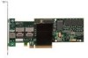
3 Intel® RAID Controller SRCSASBB8I Characteristics J8 J9 J2 J1 J6 J3 J4 J5 J7 J10 Figure 4. Card Layout AF002633 Jumper Description J1 Drive Fault LED Header J2 Dirty Cache LED Header Type 8x2 header 2-pin connector J3 Drive Activity LED Header 2-pin connector J4 Debug Connector 2-pin connector J5 Universal Asynchronous 4-pin connector Receiver/Transmitter (UART) J6 Mode 0 Select 2-pin connector Comments LED signal support for front panel drive fault per port. For connection to enclosure LED. When lit, indicates the data in the cache has not been written to disk. LED signal for drive activity. Reserved For factory and debug use. No jumper is required for normal operation. Setting the controller to Mode 0 holds the I/O processor in reset for firmware recovery. • No jumper = Normal operational mode. • Jumper = Mode 0 for firmware recovery; requires a firmware recovery utility and firmware image file. Intel® RAID Controller SRCSASBB8I Hardware User's Guide 11
-
 1
1 -
2
-
3
-
4
-
5
-
6
-
7
-
8
-
9
-
10
-
11
-
 12
12 -
 13
13 -
 14
14 -
 15
15 -
 16
16 -
 17
17 -
 18
18 -
 19
19 -
 20
20 -
 21
21 -
 22
22 -
23
-
24
-
25
-
26
-
27
-
28
-
29
-
30
-
31
-
32
-
33
-
34
-
35
-
36
 |
 |
