Intel SRCSATAWB User Guide - Page 15
Intel® RAID Controller SRCSATAWB Characteristics - lsi
 |
UPC - 735858198516
View all Intel SRCSATAWB manuals
Add to My Manuals
Save this manual to your list of manuals |
Page 15 highlights
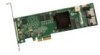
3 Intel® RAID Controller SRCSATAWB Characteristics J7 Embedded RAM J1 J2 J3 Speaker Battery Mount Points LSI* 1078 ROC J10 J6 J5 J8, ports 3 - 0 J9, ports 7 - 4 AF002341 Jumper Description Type Comments J1 Dirty cache LED 2-pin Provides signal to indicate cache needs to write header header data. J2 On-board BIOS 2-pin Default is for no jumper enable jumper J3 Serial UART port 4-pin Debug use only header J5 Drive fault LEDs 8x2 header LED signal for drive fault per port for eight ports (not available through expander) J6 I2C header (SES2) 3-pin Enclosure management support (usually a non- header expander hot-swap backplane) J7 Battery connector Daughter Connector used for optional battery backup pack card connector J8 Internal SAS/SATA SFF8087 For ports 0 - 3 port connector J9 Internal SAS/SATA SFF8087 For ports 4 - 7 port connector J10 Firmware recovery 2-pin jumper jumper This jumper needed only for flashes if the firmware is corrupted. The card does not function as a controller if this jumper is in place. Figure 4. Card Layout s Intel® RAID Controller SRCSATAWB Hardware User's Guide 10
-
 1
1 -
2
-
3
-
4
-
5
-
6
-
7
-
8
-
9
-
 10
10 -
 11
11 -
 12
12 -
 13
13 -
 14
14 -
 15
15 -
 16
16 -
 17
17 -
 18
18 -
 19
19 -
 20
20 -
21
-
22
-
23
-
24
-
25
-
26
-
27
-
28
-
29
-
30
-
31
-
32
-
33
-
34
 |
 |
