Intel SRCU31A User Guide - Page 26
Recover the Firmware in the FLASH Memory
 |
View all Intel SRCU31A manuals
Add to My Manuals
Save this manual to your list of manuals |
Page 26 highlights
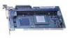
Recover the Firmware in the FLASH Memory 1. Set the Intel RAID Controller's IOP to Reset (FLASH Recovery) mode: WARNING Shock hazards may be present inside the unit in which this card is being installed. Disconnect all power cords to the unit before removal of any covers. Follow the warnings noted in the computer's user or service manual before installing this board. ONLY after all the covers are reinstalled should you reattach the power cords and power up the unit for the software installation and use. a. Take all precautions to prevent ESD damage before handling the Intel RAID Controller SRCU31. b. Power off all system components and disconnect their power cords. c. Remove the cover from the system to gain access to the PCI slots. d. Disconnect the SCSI drives from the adapter card. e. Remove the Intel RAID Controller SRCU31 from the system. f. On jumper block J7A1 move the jumper from position 2-3 to position 1-2 (see Figure 6). Re-install the adapter in the PCI slot in which it was previously installed. g. Replace the cover and reconnect all power cords. Figure 6. Jumper Positions for FLASH Update and Recovery 2. Flash the firmware. Using the bootable floppy disk with the Flash Recovery Utility from the support web site: a. Insert the floppy disk into the floppy drive. b. Power up the system. ✏ NOTE Make sure that the BIOS boot order is set to boot first from the floppy drive. As necessary, refer to the motherboard documentation. c. The Flash Recovery Utility will automatically start up. 26 Intel RAID SRCU31 Users Guide
-
 1
1 -
2
-
3
-
4
-
5
-
6
-
7
-
8
-
9
-
10
-
11
-
12
-
13
-
14
-
15
-
16
-
17
-
18
-
19
-
20
-
 21
21 -
 22
22 -
 23
23 -
 24
24 -
 25
25 -
 26
26 -
 27
27 -
 28
28 -
 29
29 -
 30
30 -
 31
31 -
32
-
33
-
34
-
35
-
36
-
37
-
38
-
39
-
40
-
41
-
42
-
43
-
44
-
45
-
46
-
47
-
48
-
49
-
50
-
51
-
52
-
53
-
54
-
55
-
56
-
57
-
58
-
59
-
60
-
61
-
62
-
63
-
64
-
65
-
66
-
67
-
68
-
69
-
70
-
71
-
72
-
73
-
74
-
75
-
76
-
77
-
78
-
79
-
80
-
81
-
82
-
83
-
84
-
85
-
86
-
87
-
88
-
89
-
90
-
91
-
92
-
93
-
94
-
95
-
96
-
97
-
98
-
99
-
100
-
101
-
102
-
103
-
104
-
105
-
106
-
107
-
108
-
109
-
110
-
111
-
112
-
113
-
114
-
115
-
116
-
117
-
118
-
119
-
120
-
121
-
122
-
123
-
124
-
125
-
126
-
127
-
128
-
129
-
130
-
131
-
132
-
133
-
134
-
135
-
136
-
137
-
138
-
139
-
140
-
141
-
142
-
143
-
144
-
145
-
146
-
147
-
148
-
149
-
150
-
151
-
152
-
153
-
154
-
155
-
156
-
157
-
158
-
159
-
160
-
161
-
162
-
163
-
164
-
165
-
166
-
167
-
168
-
169
-
170
-
171
-
172
-
173
-
174
-
175
-
176
-
177
-
178
-
179
-
180
-
181
-
182
 |
 |
