Invacare PATRIOT Owners Manual - Page 28
Adjusting Swingaway Footrest Height, Removing/installing Heel Loops
 |
View all Invacare PATRIOT manuals
Add to My Manuals
Save this manual to your list of manuals |
Page 28 highlights
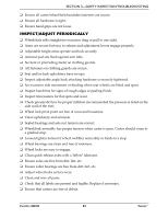
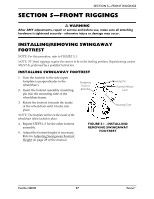
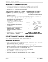
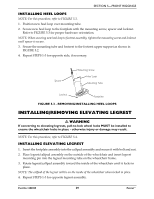
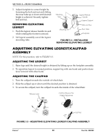
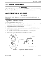
SECTION 5-FRONT RIGGINGS REMOVING SWINGAWAY FOOTREST 1. Push the footrest release lever inward while rotating the footrest outward. 2. Lift the footrest assembly out of the mounting pin of the wheelchair frame. 3. Repeat STEPS 1‐2 for opposite side, if necessary. ADJUSTING SWINGAWAY FOOTREST HEIGHT 1. Remove the footrest from the wheelchair. Refer to Installing/Removing Swingaway Footrest on page 27. 2. Remove the hex screw and coved spacer and slide the footrest up or down on its mounting tube until the desired footrest height is achieved. 3. Reassemble the hex screw and coved spacer through the footrest upper support and mounting tube as shown in FIGURE 5.2. 4. Securely tighten the hex screw and coved spacer. 5. Install the footrest assembly onto the wheelchair. Refer to Installing/ Removing Swingaway Footrest on page 27. Hex Screw Coved Spacer Footrest Footrest Upper Support Mounting Tube 6. Repeat STEPS 1‐5 for the opposite side of the wheelchair, if necessary. FIGURE 5.2 - ADJUSTING SWINGAWAY FOOTREST HEIGHT REMOVING/INSTALLING HEEL LOOPS NOTE: For this procedure, refer to FIGURE 5.2 and FIGURE 5.3. REMOVING HEEL LOOPS 1. Remove the hex screw and coved spacer that secure the mounting tube to the footrest upper support as shown in FIGURE 5.2. 2. Remove mounting tube and footrest from the footrest upper support. 3. Remove the mounting screw, spacer and locknut that secure the existing heel loop to the mounting tube and footplate as shown in FIGURE 5.3. 4. Slide existing heel loop up to remove from the mounting tube. 5. Repeat STEPS 1‐4 for opposite side, if necessary. 6. Install the new heel loop. Refer to Installing Heel Loops on page 29. Patriot™ 28 Part No 1088909
-
 1
1 -
2
-
3
-
4
-
5
-
6
-
7
-
8
-
9
-
10
-
11
-
12
-
13
-
14
-
15
-
16
-
17
-
18
-
19
-
20
-
21
-
22
-
 23
23 -
 24
24 -
 25
25 -
 26
26 -
 27
27 -
 28
28 -
 29
29 -
 30
30 -
 31
31 -
 32
32 -
 33
33 -
34
-
35
-
36
-
37
-
38
-
39
-
40
-
41
-
42
-
43
-
44
-
45
-
46
-
47
-
48
-
49
-
50
-
51
-
52
-
53
-
54
-
55
-
56
-
57
-
58
-
59
-
60
-
61
-
62
-
63
-
64
-
65
-
66
-
67
-
68
-
69
-
70
-
71
-
72
-
73
-
74
-
75
-
76
-
77
-
78
-
79
-
80
-
81
-
82
-
83
-
84
-
85
-
86
-
87
-
88
-
89
-
90
-
91
-
92
-
93
-
94
-
95
-
96
-
97
-
98
-
99
-
100
-
101
-
102
-
103
-
104
-
105
-
106
-
107
-
108
 |
 |