Invacare TRHD22FR Owners Manual - Page 20
Hand Brakes/wheel Locks
 |
View all Invacare TRHD22FR manuals
Add to My Manuals
Save this manual to your list of manuals |
Page 20 highlights
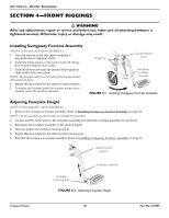
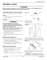
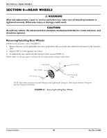
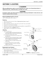
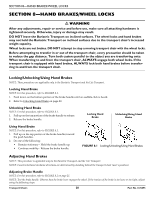
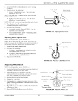
SECTION 8-HAND BRAKES/WHEEL LOCKS SECTION 8-HAND BRAKES/WHEEL LOCKS ƽ WARNING After any adjustments, repair or service and before use, make sure all attaching hardware is tightened securely. Otherwise, injury or damage may result. DO NOT leave the Bariatric Transport on inclined surfaces. The wheel locks and hand brakes may not hold the Bariatric Transport on inclined surfaces due to the transport chair's increased weight capacity. Wheel locks are not brakes. DO NOT attempt to stop a moving transport chair with the wheel locks. Before attempting to transfer in or out of the transport chair, every precaution should be taken to reduce the gap distance. Turn both casters parallel to the object you are transferring onto. When transferring to and from the transport chair, ALWAYS engage both wheel locks. If the transport chair is equipped with hand brakes, ALWAYS lock both hand brakes before transferring to and from the transport chair. Locking/Unlocking/Using Hand Brakes NOTE: These procedures are applicable only to the Bariatric Transport and the Lite Transport. Locking Hand Brake NOTE: For this procedure, refer to FIGURE 8.1. 1. Push down on the bottom portion of the brake handle until an audible click is heard. 2. Refer to Unlocking Hand Brake on page 20. Unlocking Hand Brake NOTE: For this procedure, refer to FIGURE 8.1. 1. Pull up on the top portion of the brake handle to release. 2. Release the brake handle. Locking Hand Brake Unlocking/Using Hand Brake Using Hand Brake NOTE: For this procedure, refer to FIGURE 8.1. 1. Pull up on the top portion of the brake handles toward the push handles. 2. Do one of the following: • Remain stationary ‐ Hold the brake handle up. • Continue mobility ‐ Release the brake handle. FIGURE 8.1 Locking/Unlocking/Using Hand Brakes Adjusting Hand Brakes NOTE: This procedure is applicable only to the Bariatric Transport and the Lite Transport. NOTE: Counterclockwise/clockwise directions are determined by standing behind the transport chair (user's position). Adjusting Brake Handle NOTE: For this procedure, refer to FIGURE 8.2 on page 21. NOTE: Test the brake handle. Observe how the brake lever engages the wheel. If the tension of the brake is too loose or too tight, adjust using the following steps: Transport Chairs 20 Part No.1125095
-
 1
1 -
2
-
3
-
4
-
5
-
6
-
7
-
8
-
9
-
10
-
11
-
12
-
13
-
14
-
 15
15 -
 16
16 -
 17
17 -
 18
18 -
 19
19 -
 20
20 -
 21
21 -
 22
22 -
 23
23 -
 24
24
 |
 |