JET Tools 690617 User Manual - Page 15
Feed trip cam lever, Feed direction control, Coarse feed handle, Quill lock handle, Micrometer
 |
View all JET Tools 690617 manuals
Add to My Manuals
Save this manual to your list of manuals |
Page 15 highlights
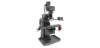
It is recommended that Feed Direction Knob be left in neutral position when not in use. Figure 8 9.9 Feed trip cam lever The Feed Trip Cam Lever (A, Figure 9) is located on left side of head behind the Manual Fine Feed Handwheel (B, Figure 9). It engages the overload clutch on the pinion shaft when positioned to the left. The Feed Trip Cam Lever stays engaged until Quill Stop (C, Figure 12) comes in contact with Micrometer Adjusting Nut (A, Figure 12) forcing it to drop out automatically, or until it is released manually by engaging the lever to the right. Figure 10 9.11 Coarse feed handle The Coarse Feed Handle (A, Figure 11) is located on right side of head. The Coarse Feed Handle is used for non-precision drilling operations and for moving quill to a specific depth. A return spring will retract spindle automatically once handle is released. 9.12 Quill lock handle The Quill Lock Handle (B, Figure 11) is located on right side of head. Rotate handle clockwise to lock quill in desired position. Rotate handle counter-clockwise to release. Figure 9 9.10 Feed direction control The Feed Direction Control (B, Figure 10) determines whether the power feed will move up, down, or not move at all. The position of knob depends upon direction of spindle rotation (see the Motor Switch section). Position of the control may be changed with the system stopped or running. If the control does not engage easily, move fine feed handwheel (A, Figure 10) back and forth to aid engagement. If spindle is rotating clockwise, in is downfeed; out is upfeed. If spindle rotation is counterclockwise, out is downfeed; in is upfeed. Neutral position is between in and out position. Figure 11 9.13 Micrometer adjusting nut The Micrometer Adjusting Nut (A, Figure 12) is located on front of head. Use for setting specific spindle depth. Secure with lock nut (B, Figure 12). 15
-
 1
1 -
2
-
3
-
4
-
5
-
6
-
7
-
8
-
9
-
 10
10 -
 11
11 -
 12
12 -
 13
13 -
 14
14 -
 15
15 -
 16
16 -
 17
17 -
 18
18 -
 19
19 -
 20
20 -
21
-
22
-
23
-
24
-
25
-
26
-
27
-
28
-
29
-
30
-
31
-
32
-
33
-
34
-
35
-
36
-
37
-
38
-
39
-
40
-
41
-
42
-
43
-
44
-
45
-
46
-
47
-
48
 |
 |
