JET Tools ESR-1650-1T User Manual - Page 9
Operation, Forming the Workpiece
 |
View all JET Tools ESR-1650-1T manuals
Add to My Manuals
Save this manual to your list of manuals |
Page 9 highlights
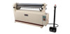
It is recommended that the ESR-1650T-3, when operated at either voltage, be connected to a dedicated 15 amp circuit with a 15 amp circuit breaker or time delay fuse. Local codes take precedence over recommendations. Refer to the Wiring Diagram at the back of this manual for more detailed wiring information. 10.0 Operation 10.1 Roll Adjustment (Figure 1 identifies machine elements.) Four adjustment screws (two in front and two in the rear) have been built into the left and right side frames. The two front adjusting screws enable the operator to raise or lower the pinch roll, so that the correct gap between the stationary and pinch rolls may be obtained to feed the desired stock into the machine. The rear adjusting screws raise or lower the idler roll which determines the degree of bend in the stock that is being fed through the machine. The right and left side frames are each equipped with a scale to aid the operator in determining. To adjust the rolls for material thickness: 1. Insert the material between the rolls from the front of the machine and raise the pinch roll until the material fits tightly. 2. Raise the idler roll equal amounts at each end, to desired position for the bend. No exact formula can be followed when making these roll adjustments because material "spring back" varies with the kind of material being formed. Only by test forming several pieces can the correct adjustments be obtained. Also, keep in mind that it is much easier to re-pass material to make a smaller radius than it is to attempt to increase a radius that was made too small. Rolls must be adjusted exactly parallel or the material will spiral during the rolling process. Measure each end of the opening with calipers if greater precision is required. NOTE: Deliberately setting the rolls non-parallel can be used to make cone shapes. The stationary, or top, roll is secured at its left end to the gear side of the machine with the cap screw and jam nut (see Figure 1). These can be adjusted if needed. 10.2 Foot Pedal Operation The shrouded foot control has pedals for instant forward or reverse motion. Push the emergency stop button for fast shut down of the slip roller. To re-start the machine, rotate the emergency stop button clockwise until it releases. 11.0 Forming the Workpiece The rolls present a pinch point and/or crush hazard. Do not place hands in close proximity to the rolls while operating. 11.1 Material Size Considerations To determine the approximate length of material needed for a desired size tube, use the following formula: C = πD where C is the circumference, π equals 3.1417 and D is the diameter. For example: To find the length of material needed (C) to form a tube 4" in diameter, multiply 3.1417 by 4". Result: 12.5667" is the circumference of approximate length of material needed. Cut several pieces of material to this length for a forming test run. Material may have to be lengthened or shortened depending upon results of the test run. If the workpiece is large, make sure it receives proper support as it exits the slip roll machine. 11.2 Flat Rolling Softer metals (copper, aluminum, etc.) can be processed through the slip roll machine to straighten, flatten, or reduce their thickness. Simply adjust the pinch roll for thickness, lower the idler roll all the way down, and feed the workpiece through (Figure 5). NOTE: The idler roll will not descend completely out of the path of the workpiece; thus, there may be a slight bend in the workpiece. By flipping the workpiece over and re-feeding it, this bend can be minimized. Figure 5 9
-
 1
1 -
2
-
3
-
 4
4 -
 5
5 -
 6
6 -
 7
7 -
 8
8 -
 9
9 -
 10
10 -
 11
11 -
 12
12 -
 13
13 -
 14
14 -
15
-
16
-
17
-
18
-
19
-
20
 |
 |
