JVC BR-DV600E 45 pg user manual for BR-DV600U/E VTR (1130KB) - Page 7
Video system connections, LCD Display - video cassette recorder
 |
View all JVC BR-DV600E manuals
Add to My Manuals
Save this manual to your list of manuals |
Page 7 highlights
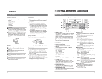
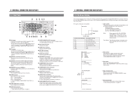
2 CONTROLS, CONNECTORS AND DISPLAYS 2-4 LCD Display 6 CH 1/3 OVER AUTO OFF DEW 40 30 20 10 0 dB CH 2/4 OVER SERVO RF 32k 44.1k 48k SLAVE PB NDF HOLD 5 AUD LOCK SP MENU LP 1 H M S F 43 2 1 Counter display section Three types of indications can be displayed in the counter display section. (1) Tape counter Normally, the indication selected with the [COUNTER] switch is shown. When the No. 516 menu switch is set to "CLOCK", the time and date are shown. ੬ See "Built-in clock setting" on page 22. (2) Menu switch In the menu switch setting mode, menu switch items are shown one at a time. Menu switch No. Setting (3) Warning code When this unit malfunctions, the nature of the problem is indicated by an error code. ੬ See "Warning indicators" on page 40. • In the Operate Off mode, "oPE-oFF" is shown. 2 Tape running indication Shows the tape running conditions. Audio dubbing mode Recording mode Rewind mode Stop mode Fast-forward mode Play mode Pause mode Reverse search mode Fast-forward search mode 3 Battery indicator When this unit is powered by a battery and the battery voltage level drops below the specified value, this indicator blinks ("off" in normal operation), to show that battery voltage is insufficient. This indicator will also blink when the Operate Off mode is engaged (since voltage output from the battery drops in this mode). 4 Cassette mark This mark lights to show that a cassette is loaded. This mark is shown even in the Operate Off mode. 5 Indicators AUTO OFF: Lights when a problem occurs in this unit. DEW: Lights when a condensation occurs. RF: Lights when the heads are clogged and the signal level drops. SERVO: Lights when the unit's servo system has stabilized. AUD LOCK: Lights when the video and audio sampling clocks (at 48 kHz) are synchronized in the Play mode. Lights in the Recording mode and EE mode. Does not light when the sampling rate is 32 kHz or 44.1 kHz. MENU: Lights in the menu switch setting mode. 32K/44.1K/48K: Shows the frequency of the digital audio signal sampling rate. In the Record and EE modes, the frequency set with No. 245 menu switch is shown. In the Play mode, the playback audio signal mode is shown. The 44.1K indication is shown only in the Play mode. PB: Lights when playback signals are output. NDF: Lights when the non-drop mode is set for time code. (U MODEL) DF: Lights when the drop mode is set for time code. (U MODEL) HOLD: Lights in the time code or user bits setting mode and in the date and time setting mode. SP/LP: Shows the recording or playback speed. Please note that LP mode recording and playback is not possible with this unit. If you try to play back a tape recorded in the LP mode, the "LP inh" indication is shown and the VCR enters the Stop mode. 6 Audio channel indication Shows the audio channel of the signal output from the rear panel's [AUDIO OUT] connectors. Indication and output signals can be switched with the front panel's [AUDIO OUTPUT] switch only when 32 kHz sampling rate signals are played back. In other modes, the indication and output signals are fixed as shown in the table below. Sampling rate Mode PB CH 1/3 ⅜ CH 2/4 32K 48K 44.1K A.DUB EE/REC PB EE/REC PB מ ⅜ ⅜ ⅜ ⅜ Fixed Fixed Fixed Fixed CH 1/3 CH 2/4 ⅜ ⅜ Fixed מ מ מ מ CH 1/3 CH 2/4 ⅜ מ מ מ מ מ PB: Play mode A.DUB: Audio Dubbing mode EE: EE mode REC: Record mode 10 3 CONNECTIONS 3-1 Video system connections Video output from a VCR, etc. Sync signal generator, etc. Input External sync signal Composite Y/C DV Component DV IN/OUT VIDEO LINE COMPONENT Y/C IN R-Y B-Y Y AUDIO CH 1/3 CH 2/4 IN IN OUT PGZ01945 OUT OUT MONITOR OUT 1 REMOTE 2 MONITOR OUT SYNC IN TIME CODE SPARE TIMER SERIAL REC PLAY DC 12V OFF Composite Y/C DV Composite Component Output Video input to a VCR, etc. Monitor TV Connecting a monitor The on-screen display can be viewed on a monitor connected to the [VIDEO MONITOR OUT] connector. Connecting video equipment Connect the video device to the appropriate connector (4 types are available). Outputs 5 Analog outputs Composite signal : [LINE OUT] connector (BNC) Component signal (Y/B-Y/R-Y) : [COMPONENT OUT] connectors (BNC x 3) YC signal : [Y/C OUT] connector (4-pin) 5 Digital output Digital video signal (conforming to IEEE 1394) [DV IN/OUT] connector Inputs Select input video signals with the No. 108 menu switch. 5 Analog inputs Composite signal : [LINE IN] connector (BNC) Component signal (Y/B-Y/R-Y) : [COMPONENT IN] connector (BNC x 3) YC signal : [Y/C IN] connector (4-pin) 5 Digital input Digital video signal (conforming to IEEE 1394) : [DV IN/OUT] connector Note: • When search pictures or low-quality video signals are input, temporary distortion of picture or sound may occur. Clean up the signals with a TBC or other processing device before inputting. Reference sync signal This unit automatically selects the sync signal as shown in the table below, depending on the presence of external sync input (SYNC IN) and video input (VIDEO IN), the No. 003 menu switch setting and operation mode. When IEEE 1394 input is selected, "INT" is selected regardless of the setting. When the No. 108 menu switch is set to "COMPONENT", the operation is the same as that performed with the No. 003 menu switch set to "AUTO" regardless of the setting. SYNC IN No VIDEO IN No EXTERNAL Playback INT Recording INT AUTO Playback INT Recording INT Yes No No Yes EXT INT INT VIDEO EXT VIDEO INT VIDEO Yes Yes EXT VIDEO EXT VIDEO INT: Internal sync EXT: External sync VIDEO: Video sync Notes: • The phase of the output signal cannot be adjusted for external sync signals. The sub carrier cannot be locked. • Plugging and unplugging the external sync or video signal connector during operation causes distortion in the picture and sound for about 10 seconds. • When signals input from the composite connector are output from the component connector, color may disappear in some parts of the left section of the monitor screen. This is not a malfunction. • The set up is not applied to signals input to the [DV IN/OUT] connector and output in EE mode (component, Y/C, composite). Input signals are recorded as is. • Use a video signal of less than 1 V(p-p) such as a black burst signal for external sync signal. • When video signals are input to the DV IN/OUT connector, distortion may occur in the lower section of the picture in the EE mode. However, recording is performed normally. • When the No. 003 menu switch is set to "EXTERNAL" and no signal is input to the [SYNC IN] connector, noise may appear in the playback picture. This is not a malfunction. 11
-
 1
1 -
 2
2 -
 3
3 -
 4
4 -
 5
5 -
 6
6 -
 7
7 -
 8
8 -
 9
9 -
 10
10 -
 11
11 -
 12
12 -
13
-
14
-
15
-
16
-
17
-
18
-
19
-
20
-
21
-
22
-
23
-
24
 |
 |
