JVC BR-DV600UA 45 pg user manual for BR-DV600U/E VTR (1130KB) - Page 6
Rear Panel, On-Screen Display - playback
 |
View all JVC BR-DV600UA manuals
Add to My Manuals
Save this manual to your list of manuals |
Page 6 highlights
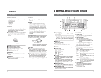
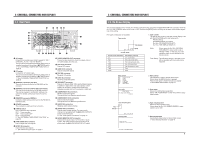
2 CONTROLS, CONNECTORS AND DISPLAYS 2-2 Rear Panel ^ & * ( ) % $ # DV IN/OUT Y/C VIDEO LINE IN COMPONENT R-Y B-Y Y AUDIO CH 1/3 CH 2/4 IN IN OUT @ ! OUT OUT MONITOR OUT 1 REMOTE 2 MONITOR OUT SYNC IN TIME CODE SPARE TIMER SERIAL REC PLAY OFF PGZ01945 DC 12V 1 2 0 9 8 7 6 5 4 3 1 AC socket Connect the provided power cable to supply AC 120 V (U MODEL), AC 220 - 240 V (E MODEL). 7 This unit can be activated automatically when power is supplied according to the setting of [TIMER] switch. ੬ See "EXTERNAL TIMER-START FUNCTION" on page 26. 2 DC socket Connect DC 12 V (XLR 4-pin). 7 This unit can be activated automatically when power is supplied according to the setting of [TIMER] switch. ੬ See "EXTERNAL TIMER-START FUNCTION" on page 26. 3 [REMOTE] connector (JVC bus) This unit can be controlled by the RM-G800 via this connector. 4 [REMOTE] connector (RS-422 Serial Connector) This unit can be controlled by an RS-422 controller. This can be changed to an RS-232C interface if re- quired. For details, contact your local JVC service center. 5 [REMOTE] connector (SERIAL) Connect a wired remote control such as the RM-G30 to control this unit. 6 [SPARE] connector This connector is empty and has no function. 7 [TIMER] switch Use to select the timer operation. REC : Timer recording OFF : Timer function OFF PLAY : Timer playback ੬ See "EXTERNAL TIMER-START FUNCTION" on page 26. 8 [TIME CODE OUT] connector Use to output time code signals. 9 [SYNC IN] connector Input reference sync signals. ੬ See "Reference sync signal" on page 11. 0 [VIDEO MONITOR OUT] connector Connect a video monitor to check the output video or on-screen display from this unit. ! [Y/C OUT] connector Outputs Y/C signals. @ [LINE OUT] connector Outputs composite signals. # [Y/C IN] connector Receives Y/C signals. $ [LINE IN] connector Receives composite signals. % [DV IN/OUT] connector Outputs or receives IEEE 1394 standard digital signals. In addition to digital video and audio signals, control signals can be input or output to/from a personal computer provided with the DV connector (i.LINK), etc. ^ [COMPONENT IN] connectors Receive component signals. The signal level is for Betacam specifications. & [COMPONENT OUT] connectors Output component signals. The signal level is for Betacam specifications. * [AUDIO IN] connectors Receives audio signals (analog). ( [AUDIO OUT] connectors 8 Outputs audio signals (analog).The output audio channel can be selected with the [AUDIO OUTPUT] switch on the front panel. ੬ See "Audio system connections" on page 12. ) [AUDIO MONITOR OUT] connector Connect to the audio input of a TV monitor or audio 9 system. The audio channel to be monitored can be selected with the [AUDIO MONITOR OUT] switch. 8 2 CONTROLS, CONNECTORS AND DISPLAYS 2-3 On-Screen Display The on-screen display can be viewed on a monitor connected to the rear panel's [VIDEO MONITOR OUT] connector when the No. 500 menu switch is set to "ON". Pressing the [MENU] button will bring up the menu switch display regardless of this setting. Five types of indication are available. Tape counter Time display STOP Mode TCR 1 2 : 0 0 : 0 0 : 0 0 Counter mode Counter mode indication CTL TCR TCG UBR UBG TIME DATE Time display contents CTL counter data Time code reader data Time code generator data User bits reader data User bits generator data Time Date 1. Tape counter The type of data shown on the tape counter display is set with the [COUNTER] switch and menu switch. Related settings [COUNTER] switch (front panel) No. 504 No. 514 Mode: Shown when the No. 504 menu switch is set to "MODE + TIME". In this case, the unit's operation status can be checked on the monitor screen. Time display: The indications shown in the table on the left are available with the counter mode indication. Menu switch 0 0 0 ~ : SERVO / SYSTEM 1 0 0 ~ : V I DEO 2 0 0 ~ : AUD I O 3 0 0 ~ : SYSTEM 4 0 0 ~ : T I ME CODE 5 0 0 ~ : ONSCREEN HM : HOUR METER 2. Menu switch This indication is used to set the menu switch. Shown when the [MENU] button is pressed. Press it once again to restore the previous display. ੬ See "MENU SWITCHES" on page 17. Hour meter ( HOUR METER ) DH : DRUM HOUR METER 0 0 0 0 0 0H 3. Hour meter Shows the rotating head usage time. Select "HM: HOUR METER" on the menu switch's group select screen. Hour Minute Tape remaining time 01 : 00 TCR 1 2 : 0 0 : 0 0 : 0 0 Warning code WARN I NG 0 2 0 1 CONDENSAT I ON ON DRUM (In case of condensation) 4. Tape remaining time Shows the tape remaining time. Shown when the No. 505 menu switch is set to "ON". 5. Warning message Automatically shown when an abnormality occurs. ੬ See "Warning indicators" on page 40. 9
-
 1
1 -
 2
2 -
 3
3 -
 4
4 -
 5
5 -
 6
6 -
 7
7 -
 8
8 -
 9
9 -
 10
10 -
 11
11 -
 12
12 -
13
-
14
-
15
-
16
-
17
-
18
-
19
-
20
-
21
-
22
-
23
-
24
 |
 |
