JVC CSBB2 Instructions - Page 1
JVC CSBB2 - 6" Subwoofer Manual
 |
UPC - 046838025976
View all JVC CSBB2 manuals
Add to My Manuals
Save this manual to your list of manuals |
Page 1 highlights
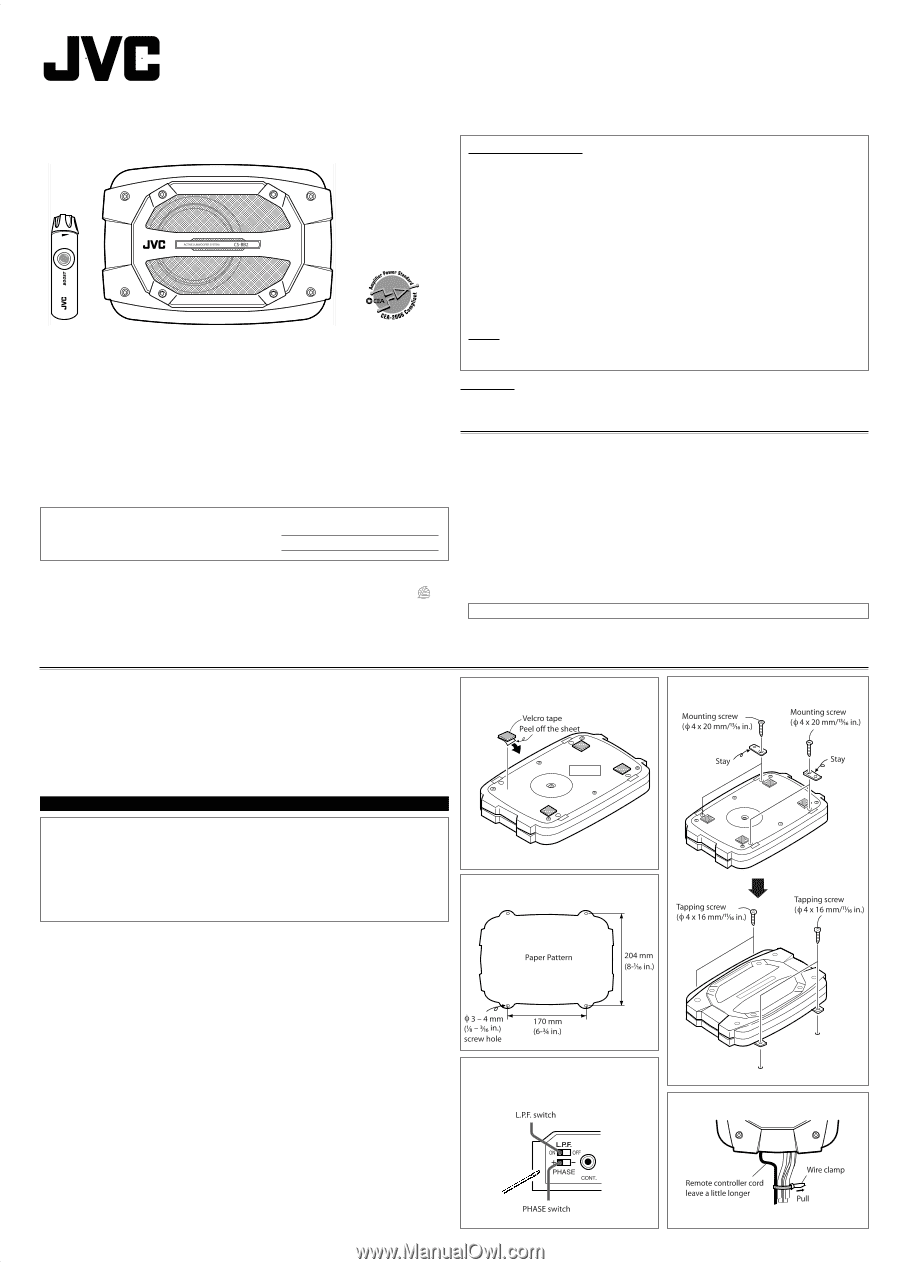
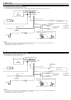
CS-BB2 ACTIVE SUBWOOFER SYSTEM: INSTRUCTIONS LVT1544-001A [J/U] INFORMATION (For U.S.A.) This equipment has been tested and found to comply with the limits for a Class B digital device, pursuant to Part 15 of the FCC Rules. These limits are designed to provide reasonable protection against harmful interference in a residential installation. This equipment generates, uses, and can radiate radio frequency energy and, if not installed and used in accordance with the instructions, may cause harmful interference to radio communications. However, there is no guarantee that interference will not occur in a particular installation. If this equipment does cause harmful interference to radio or television reception, which can be determined by turning the equipment off and on, the user is encouraged to try to correct the interference by one or more of the following measures: - Reorient or relocate the receiving antenna. - Increase the separation between the equipment and receiver. - Connect the equipment into an outlet on a circuit different from that to which the receiver is connected. - Consult the dealer or an experienced radio/TV technician for help. Caution Changes or modifications not approved by JVC could void the user's authority to operate the equipment. For safety.... • Do not raise the volume level too much, as this will block outside sounds, making driving dangerous. Thank you for purchasing a JVC product. Please read all instructions carefully before operation, to ensure your complete understanding and to obtain the best possible performance from the unit. For Customer Use: Enter the Model No. and Serial No. which are located on the top or bottom of the cabinet. Retain this information for future reference. Model No. Serial No. 0106MNMMDWJSC EN © 2006 Victor Company of Japan, Limited CAUTIONS AND NOTES This unit is designed to operate on 12 V DC, NEGATIVE ground electrical systems. • To prevent short circuits, we recommend that you disconnect the battery's negative terminal and make all electrical connections before installing the unit. • Cover the unused terminals with insulating tape to prevent them from short circuiting. • When an extension lead is used, it should be as thick and short as possible; connect it firmly with insulating tape. • Be sure to leave an appropriate space between the antenna and the wires of this unit. • When replacing the fuse, only use a 10 A fuse. • Do not let foreign objects get inside the unit. • To keep the heat dissipation mechanism running effectively, wipe the accumulated dust off periodically. • Using this subwoofer system with the volume on loud for a long period of time will exhaust the battery, while the engine is turned off or while the engine is idling. • This unit becomes very hot. Be careful not to touch the unit not only when using but for a while after using. DO NOT disassemble the units since there are no user serviceable parts inside. INSTALLATION Mount this unit on a firm surface, such as on the floor. • Since heat is generated in this unit, do not mount near flammable objects. In addition, mount in an area that will not prevent the unit from dissipating heat. • Do not mount the unit in the places subject to heat such as near a radiator, in a glove compartment or under a car mat that will prevent the unit from dissipating heat. 1 Attach the velcro tapes on the bottom as illustrated. 4 Install this unit with the supplied screws. Cautions • Never try to install this unit only with the velcro tape (supplied for skid-proof attachment). • Fix it with the tapping screws (supplied) firmly. • When mounting this unit, be sure to use the screws provided. If any other screws are used, there is a risk of loosening the unit or damaging internal parts. - Before drilling holes on the floor to install the unit, make sure that there is a sufficient space under the floor so that you do not drill holes in the fuel tank, etc. • This unit generates a strong magnetic field. Never place cassette tapes or magnetic cards nearby the unit; otherwise, data recorded in those media will be erased. Bottom 2 Drill the screw holes using the supplied paper pattern. 3 After connections, adjust the phase and volume of this unit. • For details, see "CONNECTIONS." How to use the supplied wire clamp 1
-
 1
1 -
 2
2 -
 3
3 -
 4
4
 |
 |