JVC GY-DV300U 108 pg. instruction manual on the GY-DV300U Pro-DV Camcorder (PD - Page 18
Left Side
 |
View all JVC GY-DV300U manuals
Add to My Manuals
Save this manual to your list of manuals |
Page 18 highlights
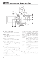
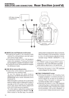
CONTROLS, INDICATORS AND CONNECTORS Left Side Section #7 MIC 1 IN MIC 2 IN EARPHONE DV Y/C OUT LINE CH-2 OUT CH-1 VIDEO OUT #6 #2#5#4 #3 #1 U [VIDEO OUT] Video output connector (RCA) Output connector for composite video signal. Outputs the input video signal and playback picture. ● When the OUTPUT CHAR. item on the DISPLAY [2/2] menu screen is set to MIX, onscreen-indicators like those shown on the LCD monitor screen can be output (black and white display). ● When the SETUP item on the SYSTEM [2/2] menu screen is set to ON, signals with setup information can be output. (black and white display) V [Y/C OUT] Y/C video output connector (4-pin) Separate YC video signal output connector. Outputs the input video signal and playback picture. ● When the OUTPUT CHAR. item on the DISPLAY [2/2] menu screen is set to MIX, onscreen-indicators like those shown on the LCD monitor screen can be output (black and white display). ● When the SETUP item on the SYSTEM [2/2] menu screen is set to ON, signals with setup information can be output. (black and white display) ● When the ASPECT item is set to LETTER on the SYSTEM [2/2] menu screen, an ID signal for identifying the wide-screen aspect is output. W [CH-1/CH-2 LINE OUT] CH-1/CH-2 audio output connector (RCA) Output connector for audio signal. In the shooting mode the input audio signal is output. In the VTR mode the playback sound is output. X [EARPHONE] Earphone jack This is a jack for connecting an earphone for monitoring the sound. Plug in an earphone or headphone with a 3.5 mm diameter plug. Monaural sound is output. Select the output sound with the MONITOR switch N. The volume of the monitor sound in the shooting mode is set with the EARPHONE LEVEL item on the TOP MENU screen. 18
-
 1
1 -
2
-
3
-
4
-
5
-
6
-
7
-
8
-
9
-
10
-
11
-
12
-
 13
13 -
 14
14 -
 15
15 -
 16
16 -
 17
17 -
 18
18 -
 19
19 -
 20
20 -
 21
21 -
 22
22 -
 23
23 -
24
-
25
-
26
-
27
-
28
-
29
-
30
-
31
-
32
-
33
-
34
-
35
-
36
-
37
-
38
-
39
-
40
-
41
-
42
-
43
-
44
-
45
-
46
-
47
-
48
-
49
-
50
-
51
-
52
-
53
-
54
-
55
-
56
-
57
-
58
-
59
-
60
-
61
-
62
-
63
-
64
-
65
-
66
-
67
-
68
-
69
-
70
-
71
-
72
-
73
-
74
-
75
-
76
-
77
-
78
-
79
-
80
-
81
-
82
-
83
-
84
-
85
-
86
-
87
-
88
-
89
-
90
-
91
-
92
-
93
-
94
-
95
-
96
-
97
-
98
-
99
-
100
-
101
-
102
-
103
-
104
-
105
-
106
-
107
-
108
 |
 |
