JVC GY-HD250U GY-HD250 Studio Reference Manual v1.12 (Oct. 2008) (66 pages, 18 - Page 57
Connection to a balanced audio Intercom system
 |
UPC - 046838027383
View all JVC GY-HD250U manuals
Add to My Manuals
Save this manual to your list of manuals |
Page 57 highlights
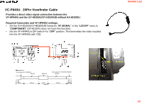
Version 1.12 Connection to a balanced audio Intercom system Connect ion between XLR-3pin and the RM-HP250AU When connecting to a 2 wire balanced system such as Audio-com ® connect three pin microphone XLRs to the RM-HP250AU as shown in Fig. 3. XLR-3pin RM-HP250AU REAR PANEL 1 2 3 Fig. 3 Audiocom ® system XLR pin assignment of each intercom Pin # Pin-1 Pin-2 Pin-3 Audiocom GND Balanced Audio(C) + DC Power Balanced Audio(H) + DC Power Settings of the RM-HP250AU • S301 on the MAIN board is set to "2W" (Side tone adjustment* is required). * Refer on page 1-9 of the RM-HP250AU service manual(No. HC025) 56
-
 1
1 -
2
-
3
-
4
-
5
-
6
-
7
-
8
-
9
-
10
-
11
-
12
-
13
-
14
-
15
-
16
-
17
-
18
-
19
-
20
-
21
-
22
-
23
-
24
-
25
-
26
-
27
-
28
-
29
-
30
-
31
-
32
-
33
-
34
-
35
-
36
-
37
-
38
-
39
-
40
-
41
-
42
-
43
-
44
-
45
-
46
-
47
-
48
-
49
-
50
-
51
-
 52
52 -
 53
53 -
 54
54 -
 55
55 -
 56
56 -
 57
57 -
 58
58 -
 59
59 -
 60
60 -
 61
61 -
 62
62 -
63
-
64
-
65
-
66
 |
 |

Version 1.12
Pin #
Audiocom
Pin-1
GND
Pin-2
Balanced Audio(C) + DC Power
Pin-3
Balanced Audio(H) + DC Power
3
2
1
RM-HP250AU REAR PANEL
Fig. 3
Audiocom ® system
Settings of the RM-HP250AU
•
S301
on the MAIN board is set to “
2W
” (Side tone adjustment* is required).
* Refer on page 1-9 of the RM-HP250AU service manual(No. HC025)
XLR pin assignment of each intercom
Connect ion between XLR-3pin and the RM-HP250AU
XLR-3pin
When connecting to a 2 wire balanced system such as Audio-com ® connect three pin microphone XLRs to
the RM-HP250AU as shown in Fig. 3.
Connection to a balanced audio Intercom system
56