JVC GYHD110U Instructions - Page 14
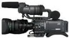
Controls, Indicators And Connectors - lense
 |
UPC - 046838027345
View all JVC GYHD110U manuals
Add to My Manuals
Save this manual to your list of manuals |
Page 14 highlights
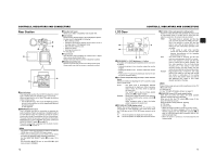
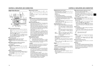
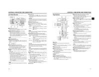
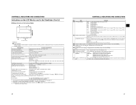
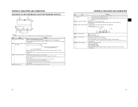
CONTROLS, INDICATORS AND CONNECTORS Indications on the LCD Monitor and in the Viewfinder (Cont'd) 1 2 3 7 0 4 9 86 5 STATUS 1 Screen • STATUS 1 In addition to the information on the STATUS 0 screen, this screen displays the following items. No. Item Contents 1 VIDEO FORMAT display Displays the currently selected video format. Allows you to select the REC item on the VIDEO FORMAT menu screen. X See page 64. You can switch this display ON/OFF using the FORMAT item on the LCD/VF [2/3] menu screen. X See page 75. 2 Time Code (TC)/User's Bits Indicates the time code (h:m:s:frame) or user's bits data. (UB) indication (Example) Time code TC 00 : 00 : 00 : 00 3 Remaining tape indication 4 Voltage indication Colon (:) when non-drop frame mode Dot (.) when drop frame mode User's bits UB FF EE DD 20 Whether or not to display this item is set with the TC/UB item on the LCD/VF [2/3] menu screen. X See page 75. Whether the time code or user's bits should be shown is selected with the TC DISPLAY switch inside the LCD door. Remaining tape indication (displayed in 1-minute steps) This indicator blinks when remaining tape time is equivalent to less than 3 minutes. Whether or not to display this item is set with the TAPE REMAIN item on the LCD/VF [2/3] menu screen. X See page 75. * When inserting a brand-new tape, the remaining tape time is not indicated. When the tape has been run, the indication will appear. * The remaining tape indication is to be regarded only as a guide. * When the unit is used at low temperatures, it may take a while before the indication of the remaining tape time appears. (Example) 7.0V: Indicates remaining battery level in 0.1V steps. CONTROLS, INDICATORS AND CONNECTORS No. Item Contents 5 Audio sampling frequency in- 32 K : Indicated when the AUDIO MODE item on the AUDIO/MIC [1/2] menu screen is set to 32 K. (Au- dication dio is recorded with 12-bit, 32 kHz sampling.) 48 K : Indicated when the AUDIO MODE item on the AUDIO/MIC [1/2] menu screen is set to 48 K. (Au- dio is recorded with 16-bit, 48 kHz sampling.) X See page 72. 6 Audio level meter indication Displays the CH-1, CH-2 audio level meters. Whether or not to display this item is set with the AUDIO item on the LCD/VF [2/3] menu. X See page 75. 7 Standard audio level indication The level at which audio is recorded on the tape is indicated by "O". -20 dB, -12 dB X See "AUDIO REF.LEVEL" on page 72. 8 Iris indicator display 9 Iris F-value indication 0 Filter position indication -20 dB -12 dB CH-1 CH-2 OO O O O O O O O O O \\\] O O O O O O O O O \\\] M: Iris set higher than normal b: Iris set to normal N: Iris set lower than normal Indicates the F-number of the connected lens. OPEN, F2, F2.8, F4, F5.6, F8, F11, F16, CLOSE It is not displayed when the lens is removed. For some lenses, no display appears. The indication can be switched ON/OFF with the F.NO/IRIS IND. item on the LCD/VF [1/3] menu screen. X See page 74. Indicates the current filter position. No display: FILTER OFF ND1: FILTER ND1 (1/4ND) ND2: FILTER ND2 (1/16ND) The indication can be switched ON/OFF with the FILTER item on the LCD/VF [1/3] menu screen. X See page 74. 22 23
-
 1
1 -
2
-
3
-
4
-
5
-
6
-
7
-
8
-
 9
9 -
 10
10 -
 11
11 -
 12
12 -
 13
13 -
 14
14 -
 15
15 -
 16
16 -
 17
17 -
 18
18 -
 19
19 -
20
-
21
-
22
-
23
-
24
-
25
-
26
-
27
-
28
-
29
-
30
-
31
-
32
-
33
-
34
-
35
-
36
-
37
-
38
-
39
-
40
-
41
-
42
-
43
-
44
-
45
-
46
-
47
-
48
-
49
-
50
-
51
 |
 |
