JVC GYHD110U Instructions - Page 8
ZOOM Lens, Front - manual
 |
UPC - 046838027345
View all JVC GYHD110U manuals
Add to My Manuals
Save this manual to your list of manuals |
Page 8 highlights
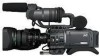
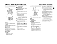
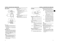
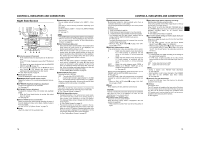
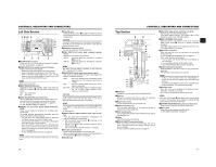
CONTROLS, INDICATORS AND CONNECTORS ZOOM Lens Th16 x 5.5BRMU 32 1 RET M A W T 4 5 6 78 9 0 d MACRO ab c 1FOCUS ring Manual focus ring. 2ZOOM lever/ring This is the manual zoom ring equipped with a zoom lever. To adjust the zoom manually, turn the zoom mode knob b to position "M". 3IRIS ring Manual iris ring. To activate the auto iris feature, set the Iris Mode switch 7 to "A". 4[VTR] VTR trigger button To start/stop shooting. 5[RET] Return video button You can only monitor the return video signal from the VTR from the viewfinder, LCD monitor and video signal connector while this button is pressed. When you set the LENS RET item to "FOCUS ASSIST" in the SWITCH MODE menu screen, you can use this button as the FOCUS ASSIST button. X See page 71. 6ZOOM servo control lever To operate the servo zoom feature with this lever, set the ZOOM knob b to "S". • Pressing the "W" section of this lever increases the angle of the lens for a wider shooting angle. • Pressing the "T" section of this lever narrows the lens angle perspective for telephoto shots. • Pushing harder changes the speed of the zoom. 7IRIS mode switch A : Activates the auto iris feature. M : Allows manual iris control. 8Momentary auto iris button When the IRIS mode switch 7 is at "M", pushing this button activates the Auto Iris Function while it is held down only. 9[S] IRIS speed adjusting control For adjusting the iris operation speed. MEMO If the speed becomes too fast, hunting may occur. To avoid the phenomena described above, perform adjustment again. 0FILTER thread Protect the lens with a clear filter or UV filter by screwing the filter onto the thread inside the lens hood from the front. Other filters can be used for various effects. aZOOM servo connector Connect an optional zoom servo unit here. b[ZOOM] ZOOM mode knob S : Servo zoom mode. Allows operation by the zoom servo control lever 6. M : Manual zoom mode. Allows zoom control by the zoom lever/ring 2. cBACK FOCUS ring/fixing screw For back focus adjustment only. Secure with the screw knob after adjustment. X See "Back Focus Adjustment" on page 44. dMacro focusing ring (for close-up shooting) By rotating this ring in the direction of the arrow, close-up shooting of very small objects becomes possible. Normal focus adjustment and zooming are not available in the macro mode. To shoot images in the macro mode, set the focus ring 1 to the infinite position (f) and the zoom ring 2 to the maximum wide-angle position. To adjust the focus of the macro image, rotate this ring in the direction of the arrow until the object is focused. CAUTION • The back-focus knob is located close to the macro ring, be careful not to mistake the back-focus knob for the macro ring. • After the required operation, be sure to return the macro focusing ring to the normal position. X See "Attaching the Zoom Lens" on page 30. X See "Back Focus Adjustment" on page 44. 10 CONTROLS, INDICATORS AND CONNECTORS Front Section 32 1 4 8 7 5 6 1Shoe Makes it possible to mount separately sold lights and accessories. 2Knob This is the mounting knob for the microphone holder 3. 3Microphone holder Makes it possible to attach the provided microphone or a separately sold microphone. X See "Attaching the Microphone (Provided)" on page 30. 4Front tally lamp This lamp lights up when the GY-HD110 enters the record mode. It blinks during the transition to the record mode. When the tape has run out, or the VTR enters the warning mode, it blinks quickly. • Use the FRONT TALLY item on the OTHERS [1/2] menu screen to select whether or not the lamp should light and the lighting pattern. X See page 80. 5[LENS] Lens control connector Connect 12-pin lens control cable from lens here. Pin No. Function Pin No. Function 1 Return switch 7 Iris position 2 VTR trigger 8 IRIS A/R INPUT 3 GND 9 EXTENDER position 4 Lens AUTO/MANU control 10 ZOOM position 5 IRIS control 11 - 6 +12V DC 12 - 6[ZEBRA] Zebra switch When this switch is ON, a zebra pattern is imposed on the viewfinder or LCD areas having luminance levels in accordance with the menu settings made for the video signal. This pattern can be used as a reference for manual adjustment of the lens iris. Zebra patterns are also displayed during color bar display when this switch is set to ON. • The default value is 70% - 80%. The luminance level can be changed with the ZEBRA setting in the LCD/VF [1/3] menu screen. X See page 74. While this switch is pressed to the SKIN AREA side, the color tone areas specified with the SKIN COLOR ADJUST item on the ADVANCED PROCESS menu are indicated in the viewfinder. The switch returns to the OFF position when released. X See "How to Use Skin Detail" on page 86. * The Skin Detail color tone areas are not indicated while the color bar or VTR playback picture is shown in the viewfinder or on the LCD monitor. 7[AWB] Auto white balance button When the WHT.BAL switch c on page 15 is set to A or B and you press this button, the white balance is automatically adjusted. * It is not activated in preset, full auto shooting, full auto white balance and color bar modes. X See "White Balance Adjustment" on page 45. 8Lens mounting ring/Lens lock lever Hold the lens and use the lever to turn the ring anticlockwise to release lens. To mount lens make sure the lens guide pin fits well, and then turn the ring clockwise until firm. X See "Attaching the Zoom Lens" on page 30. 11
-
 1
1 -
2
-
 3
3 -
 4
4 -
 5
5 -
 6
6 -
 7
7 -
 8
8 -
 9
9 -
 10
10 -
 11
11 -
 12
12 -
 13
13 -
14
-
15
-
16
-
17
-
18
-
19
-
20
-
21
-
22
-
23
-
24
-
25
-
26
-
27
-
28
-
29
-
30
-
31
-
32
-
33
-
34
-
35
-
36
-
37
-
38
-
39
-
40
-
41
-
42
-
43
-
44
-
45
-
46
-
47
-
48
-
49
-
50
-
51
 |
 |
