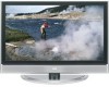
JVC LT40X776 Instructions - Page 16
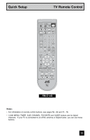
VCR Connection, Notes, Diagram #1 - user manual
 |
UPC - 046838019371
View all JVC LT40X776 manuals
Add to My Manuals
Save this manual to your list of manuals |
Page 16 highlights
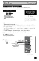
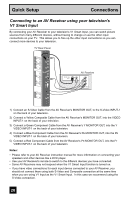
Quick Setup Connections VCR Connection Notes: • Green, blue and red are the most common colors for DVD cables. Some models may vary colors. Please consult the user's manual for your DVD player for more information. • Be careful not to confuse the red DVD cable with the red audio cable. It is best to complete one set of connections (DVD or audio output) before starting the other to avoid accidentally switching the cables. • You may also connect the DVD player to Input 1. Diagram #1 VCR IN OUT V LR IN OUT OR Cable or Antenna Output Two-Way Splitter IN (Attachment) OUT OUT Coaxial Cable (Attachment) INPUT 1 S-VIDEO VIDEO R - AUDIO - L S-VIDEO VIDEO R - AUDIO - L (7V5HΩF/UHF) INPUT 2 INPUT 3 DIGITAL IN AUDIO INPUT 1 COMPONENT VIDEO R - AUDIO - L Y Pr Pb R - AUDIO - L ATSC / DIGITAL CABLE IN TV Rear Panel DIGITAL-IN CABLE CARD Green Blue Red AUDIO OUT Y PB PR R L OUT AUDIO OUT R L DVD Player (OPTIONAL) i.LINK IN/OUT S400(TS) Note: • If this connection setup does not work for you, try the connection setup on page 17. 16
-
 1
1 -
2
-
3
-
4
-
5
-
6
-
7
-
8
-
9
-
10
-
 11
11 -
 12
12 -
 13
13 -
 14
14 -
 15
15 -
 16
16 -
 17
17 -
 18
18 -
 19
19 -
 20
20 -
 21
21 -
22
-
23
-
24
-
25
-
26
-
27
-
28
-
29
-
30
-
31
-
32
-
33
-
34
-
35
-
36
-
37
-
38
-
39
-
40
-
41
-
42
-
43
-
44
-
45
-
46
-
47
-
48
-
49
-
50
-
51
-
52
-
53
-
54
-
55
-
56
-
57
-
58
-
59
-
60
-
61
-
62
-
63
-
64
-
65
-
66
-
67
-
68
-
69
-
70
-
71
-
72
-
73
-
74
-
75
-
76
-
77
-
78
-
79
-
80
-
81
-
82
-
83
-
84
-
85
-
86
-
87
-
88
-
89
-
90
-
91
-
92
-
93
-
94
-
95
-
96
 |
 |
