JVC MV40US Instruction Manual - Page 13
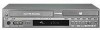
Rear View, INDEX
 |
UPC - 046838023217
View all JVC MV40US manuals
Add to My Manuals
Save this manual to your list of manuals |
Page 13 highlights
Rear View INDEX EN 13 AB C D E FG H I DVD DIGITAL COMPONENT PCM/ AUDIO OUT VIDEO OUT STREAM S VIDEO S VIDEO VIDEO OPTICAL Y COAXIAL PB PR VIDEO VIDEO L AUDIO R L AUDIO R OUTPUT INPUT L-1 DVD DVD/VCR S VIDEO DVD VCR IN L AUDIO R REMOTE IN OUT OUTPUT DVD/VCR ANT. LOOP OUT TV OUT VHF/UHF A Region Number ੬ pg. 9 B AC Power Cord ੬ pg. 17 C Cooling Fan ● This prevents the temperature from rising inside the unit. Do not remove it. ● Install the unit so as not to block the area around the fan. ● The cooling fan on the rear of the unit may be activated even if the unit is turned off when "AUTO CLOCK" is set to "ON" (੬ pg. 20). D Digital Audio Output Connectors [DIGITAL AUDIO OUT (COAXIAL/OPTICAL)] (DVD deck only) ੬ pg. 65, 68 E Component Video Output Connectors [COMPONENT VIDEO OUT (Y/PB/PR)] ੬ pg. 17 ● This component video output enables you to watch the images on the VCR deck in Progressive scan mode, refer to "VHS Progressive Scan" (੬ pg. 45). JK F S-video/Video/Audio Output Connectors [S-VIDEO/ VIDEO/AUDIO OUTPUT] (DVD deck only) ੬ pg. 17 G S-video/Video/Audio Input Connectors [S-VIDEO/ VIDEO/AUDIO INPUT (L-1)] ੬ pg. 64 H S-video/BNC Video/Audio Output Connectors [S-VIDEO/VIDEO/AUDIO OUTPUT] ੬ pg. 17 I Antenna Input Connectors [VHF/UHF IN (DVD/VCR)] ੬ pg. 17 J Remote In Connector* (REMOTE IN) * There is currently no compatible remote control unit available. K Antenna Output Connectors [VHF/UHF OUT (ANT. LOOP OUT/TV OUT)] ੬ pg. 17
-
 1
1 -
2
-
3
-
4
-
5
-
6
-
7
-
 8
8 -
 9
9 -
 10
10 -
 11
11 -
 12
12 -
 13
13 -
 14
14 -
 15
15 -
 16
16 -
 17
17 -
 18
18 -
19
-
20
-
21
-
22
-
23
-
24
-
25
-
26
-
27
-
28
-
29
-
30
-
31
-
32
-
33
-
34
-
35
-
36
-
37
-
38
-
39
-
40
-
41
-
42
-
43
-
44
-
45
-
46
-
47
-
48
-
49
-
50
-
51
-
52
-
53
-
54
-
55
-
56
-
57
-
58
-
59
-
60
-
61
-
62
-
63
-
64
-
65
-
66
-
67
-
68
-
69
-
70
-
71
-
72
-
73
-
74
-
75
-
76
-
77
-
78
-
79
-
80
-
81
-
82
-
83
-
84
-
85
-
86
-
87
-
88
 |
 |
